5-36
Motor 2 V/f Pattern: E3
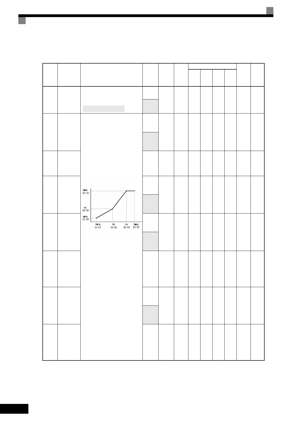
User constants for motor 2 V/f characteristics are shown in the following table.
* 1. These are values for a 200 V Class Inverter. Values for a 400 V Class Inverter are double.
* 2. The factory setting will change when the control method is changed. The V/f control factory settings are given.
* 3. When C6-01 = 1, the upper limit is 400.0.
* 4. When C6-01 = 0, the upper limit is 150.0.
Con-
stant
Num-
ber
Name Description
Setting
Range
Factory
Setting
Change
during
Opera-
tion
Control Methods
MEMO
BUS
Regis-
ter
Page
V/f
V/f
with
PG
Open
Loop
Vec-
tor
Flux
Vec-
tor
E3-01
Motor 2
control
method
selection
0: V/f control
1: V/f control with PG
2: Open-loop vector control
0 to 2
0 No A A A A 319H -
0 to 3
E3-02
Motor 2
max. out-
put fre-
quency
(FMAX)
To set V/f characteristics in a
straight line, set the same values
for E3-05 and E3-07.
In this case, the setting for E3-06
will be disregarded.
Always ensure that the four fre-
quencies are set in the following
manner:
E3-02 (FMAX) ≥ E3-04 (FA) >
E3-05 (FB) > E3-07 (FMIN)
40.0 to
400.0
*4
60.0
Hz
NoAAAA31AH-
40.0 to
300.0
*3
E3-03
Motor 2
max. volt-
age
(VMAX)
0.0 to
255.0
*1
200.0
V
*2
NoAAAA31BH-
E3-04
Motor 2
max. volt-
age fre-
quency
(FA)
0.0 to
400.0
*4
60.0
Hz
NoAAAA31CH-
0.0 to
300.0
*3
E3-05
Motor 2
mid. out-
put fre-
quency 1
(FB)
0.0 to
400.0
*4
3.0 Hz
*2
No A A A No 31DH -
0.0 to
300.0
*3
E3-06
Motor 2
mid. out-
put fre-
quency
voltage 1
(VC)
0.0 to
255.0
*1
15.0 V
*1
No A A A No 31EH -
E3-07
Motor 2
min. out-
put fre-
quency
(FMIN)
0.0 to
400.0
*4
1.5 Hz
*2
NoAAAA31FH-
0.0 to
300.0
*3
E3-08
Motor 2
min. out-
put fre-
quency
voltage
(VMIN)
0.0 to
255.0
*1
9.0 V
*1
No A A A No 320H -
3: Flux vector control
Output voltage (V)
Frequency (Hz)

 Loading...


