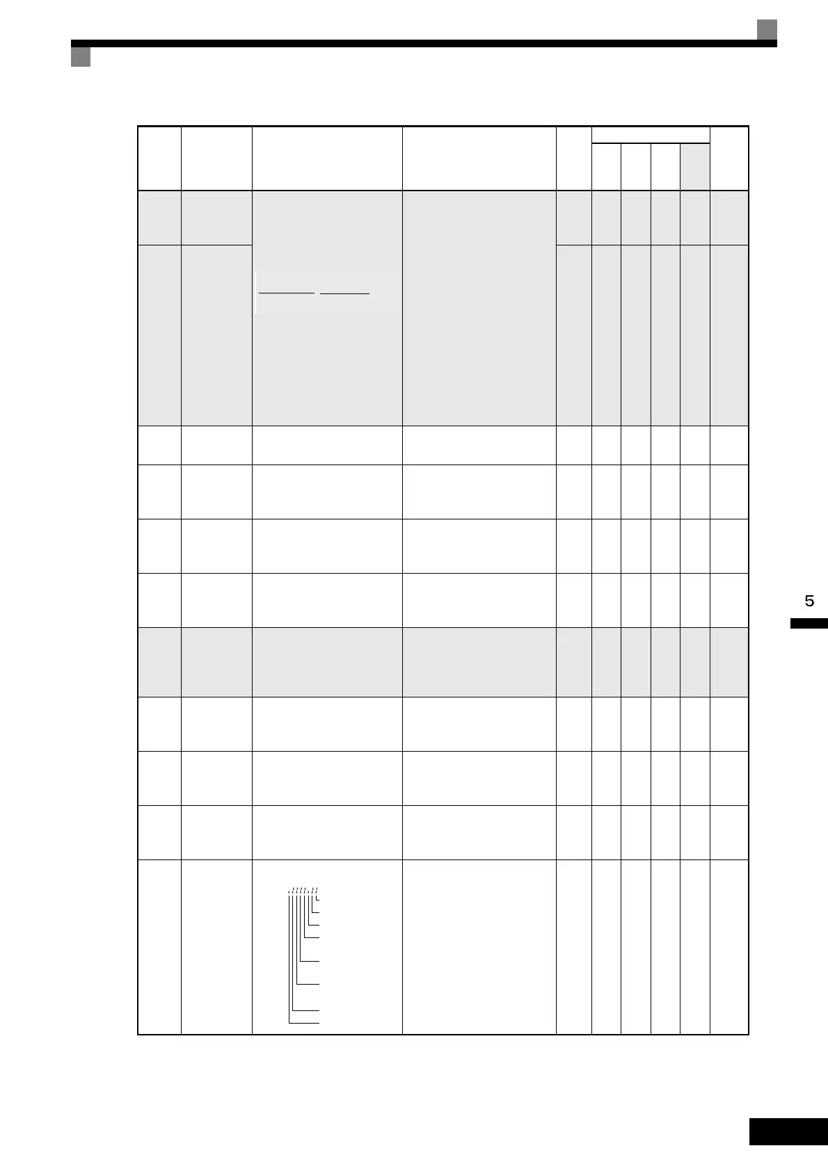
User Constant Tables
5-77
U1-29
Output
power lower
4 digits
Monitors the Inverter’s out-
put power. The display is
split into upper digits and
lower digits in the following
way.
Example: If the output
power is 12345678.9 kWh,
the display will be as fol-
lows:
U1-29: 678.9 kWH
U1-30: 12345 MWH
Range: 0.0 to 32767999.9
(Cannot be output.)
kWH A A A A 05CH
U1-30
Output
power upper
5 digits
MW
H
A A A A 05DH
U1-31 LED check
Lights all LEDs on the Dig-
ital Operator JVOP-161.
(Cannot be output.) - A A A A 3CH
U1-32
ACR out-
put of q axis
Monitors the current control
output value for the motor
secondary current.
10 V: 100%
(0 to ± 10 V possible)
0.1
%
No No A A 5FH
U1-33
ACR out-
put of d axis
Monitors the current control
output value for the motor
excitation current.
10 V: 100%
(0 to ± 10 V possible)
0.1
%
No No A A 60H
U1-34
OPE fault
constant
Shows the first constant
number where an OPE fault
was detected.
(Cannot be output.) - A A A A 61H
U1-35
Zero-servo
movement
pulses
Shows the number of PG
pulses times 4 for the move-
ment range when stopped at
zero.
(Cannot be output.) 1 No No No A 62H
U1-36
PID input
volume
PID feedback volume
Given as maximum fre-
quency/100%
10 V: Max. frequency
(0 to ± 10 V possible)
0.01
%
AAAA63H
U1-37
PID output
volume
PID control output
Given as maximum fre-
quency/100%
10 V: Max. frequency
(0 to ± 10 V possible)
0.01
%
AAAA64H
U1-38
PID target
value
PID target value
Given as maximum fre-
quency/100%
10 V: Max. frequency
0.01
%
AAAA65H
U1-39
MEMO-
BUS
communica-
tions error
code
Shows MEMOBUS errors.
(Cannot be output.) - A A A A 66H
Con-
stant
Number
Name Description
Output Signal Level Dur-
ing Multi-Function Analog
Output
Min.
Unit
Control Methods
MEMO
BUS
Regis-
ter
V/f
V/f
with
PG
Open
Loop
Vec-
tor
Flux
Vec-
tor
U1-30 U1-29
.
kWH
1: CRC error
1: Data length error
Not used (always 0).
1: Parity
error
1: Overrun
error
1: Framing
error
1:
Timeout
Not used (always 0).
U1-39=

 Loading...


