5-10 IM 04P02B01-01E
Explanation
Channel Range
The only case when an alarm can be set on multiple channels simultaneously is when
the channels are set to the same range type (for example channel 01 and 02 are set to 2
V range). For channels on which scaling is set, the channels must be set to the same
range type, same span values, and same scaling values.
Alarm Type
Symbol Name Note
H High limit alarm
L Low limit alarm
h Difference high limit alarm Can be specified on channels set to
delta computation.
l Difference low limit alarm Can be specified on channels set to
delta computation.
R High limit on rate-of-change alarm
r Low limit on rate-of-change alarm
T Delay high limit alarm*
t Delay low limit alarm*
* Selectable only when the alarm delay function is enabled. See section 7.15.
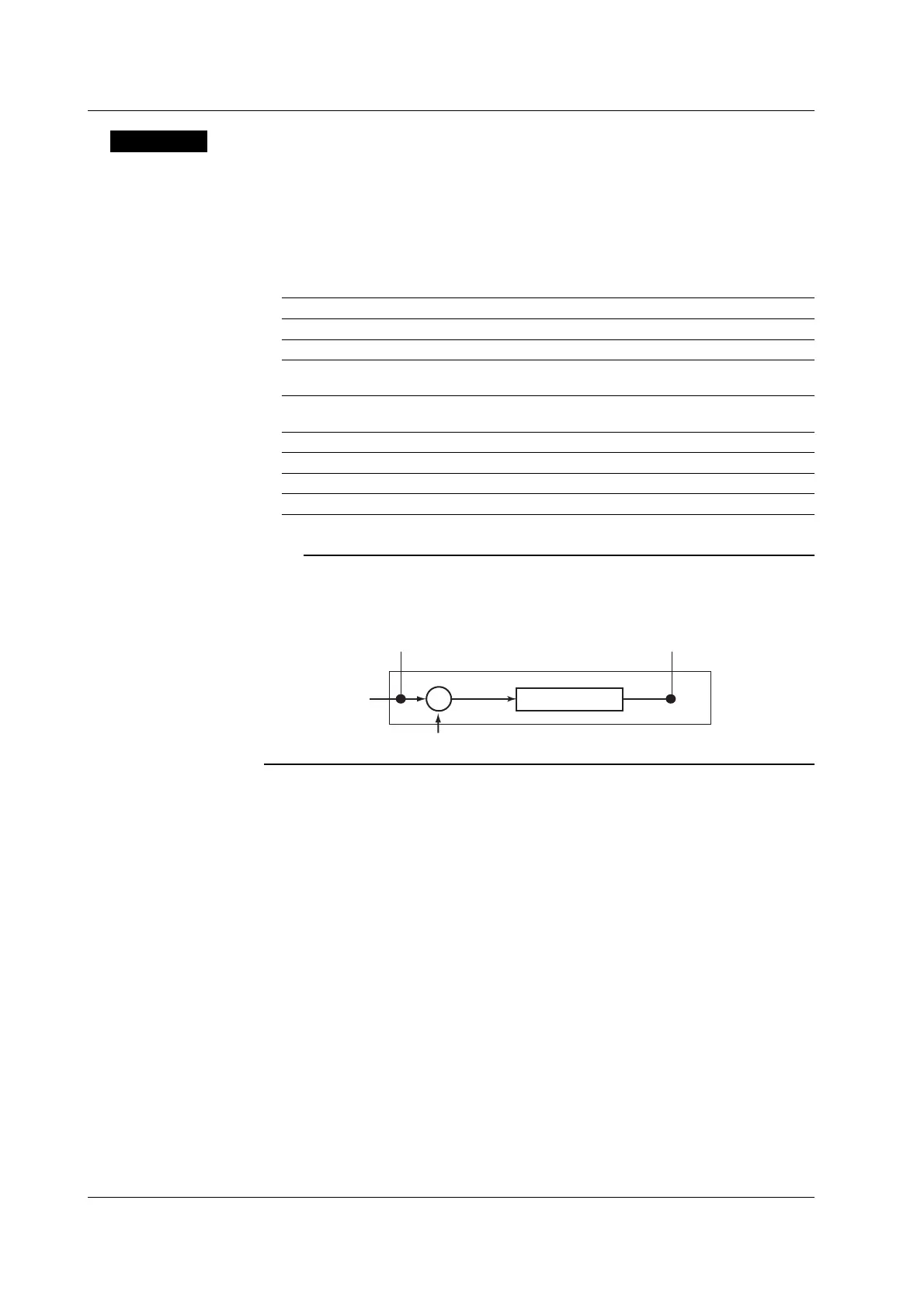
Note
On channels set to delta computation, alarms can be detected on the values illustrated in the
figure below.
Input value
Measured value on the reference channel
Alarm on a channel set to delta computation
Alarm
H, L, R, r, T, and t
Alarm
h and l
Measured value
–
If high limit on rate-of-change alarm or low limit on rate-of-change alarm is specified, set
the interval over which the rate-of-change is calculated.
If delay high limit alarm or delay low limit alarm is specified, set the delay time.
<Related Topics>
Setting the interval of the high limit on rate-of-change alarm or low limit on rate-of-
change alarm: Section 7.1
Setting the delay time of delay high limit alarm or delay low limit alarm: Section 6.10
Enabling the alarm delay function: Section 7.15
Setting the alarm hysteresis: Section 7.1
Alarm Value
• High Limit Alarm/Low Limit Alarm and Delay High Limit Alarm/Delay Low Limit
Alarm
The following values can be specified.
• For DC voltage, TC, and RTD input: Values within the measurable range in the
specified range (example: –2.000 to 2.000 V for the 2 V range).
• For ON/OFF input (DI): 0 or 1.
• For linear scaling (1-5V, scaling, and square root): A value within –5 to 105% of the
scaling span except within the range of –20000 to 30000 (excluding the decimal
point).
5.2 Setting the Alarm
 Loading...


