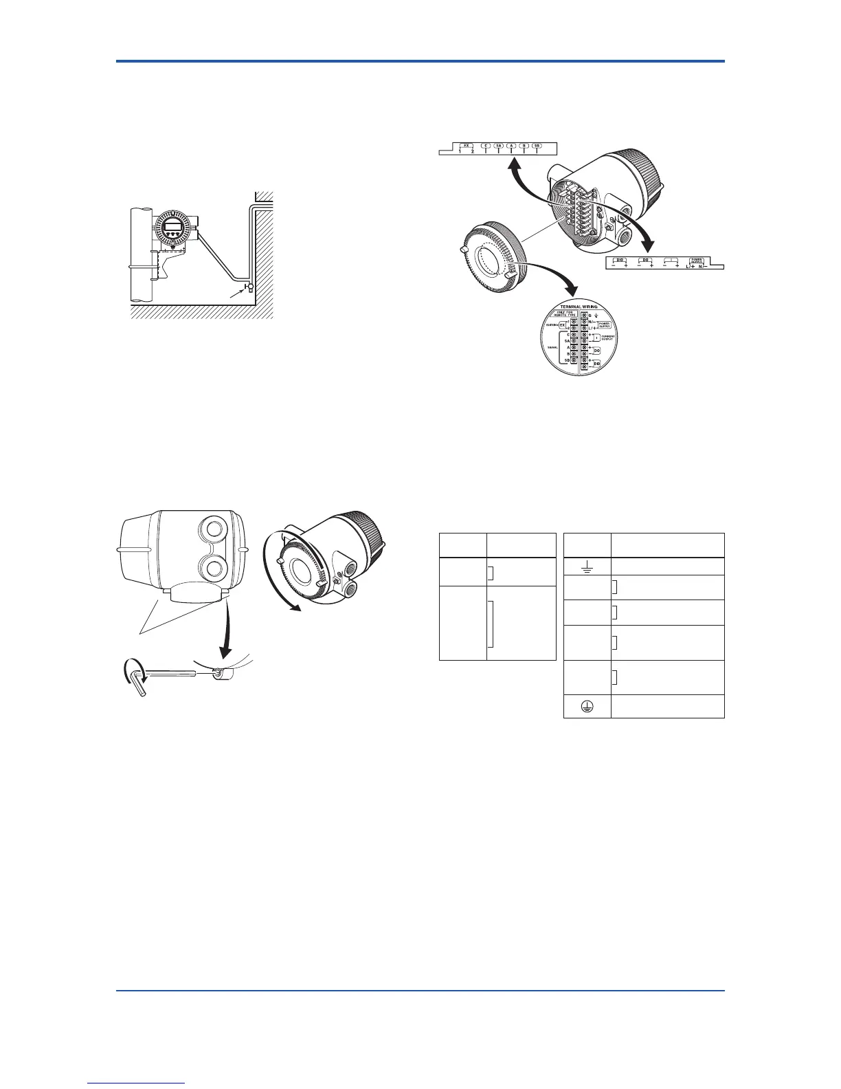
(3) Conduit Wiring
When wiring the conduits, pass the conduit through the
wiring connection port, and utilize the waterproof gland to
preventwaterfromowingin.Placetheconduitpipeon
an angle as shown in Figure 4.3.4.
Install a drain valve at the low end of the vertical pipe, and
open the valve regularly.
Drain valve
Figure 4.3.4 Conduit Wiring
4.3.4 Wiring Connections for AXFA14
(1) Removing Cover
Loosen cover locking screw 2 clockwise using a
hexagonal wrench (nominal size 3) to unlock the cover.
(Upon shipment from the manufacturing plant, the cover
isunlocked.)Holdtheowmeterwithyourhandand
remove the cover by turning it in the direction of the arrow
as shown below.
F0437.ai
Cover locking screws
1
2
Figure 4.3.5 Removing the Terminal Box Cover for AXFA14
Remote Converter
(2) TerminalConguration
When the cover is removed, the connection terminals will
bevisible.Theterminalcongurationlabelsareattached
in the locations shown in Figure 4.3.6.
Figure4.3.6 TerminalCongurationforAXFA14Remote
Converter
The description of the terminal symbols is shown in Table
4.3.1.
For F
OUNDATIONeldbusprotocol,refertoIM01E20F02-
01E.
For PROFIBUS PA protocol, refer to IM 01E20F12-01E.
Table 4.3.1 Terminal Symbols for AXFA14 Remote
Converter
Terminal
Symbols
Description
Terminal
Symbols
Description
EX1
EX2
Excitation
current output
Functional grounding
N/–
L/+
Power supply
C
SA
A
B
SB
Flow singal
input
I+
I–
Current output 4 to 20mA
DC
DO+
DO–
Pulse output/
Alarm output/
Status output
DIO+
DIO–
Alarm output/
Status output/
Status input
Protective grounding
(Outside of the terminal)
(3) Precautions for Wiring of Power Supply
Cables
When connecting to the power supply, observe the points
below. Failure to comply with these warnings may result
in an electric shock or damage to the instrument.
 Loading...
