3. Installation
WARNING
Installationofthemagneticowmetermustbe
performed by expert engineer or skilled personnel.
No operator shall be permitted to perform procedures
relating to installation.
Installation Location Precautions
Select the installation location with consideration to the
following items to ensure long-term stable operation of
the instrument.
Ambient Temperature:
Avoid installing the instrument in locations with constantly
uctuatingtemperatures.Ifthelocationissubjectto
radiant heat from the plant, provide heat insulation or
improve ventilation.
Atmospheric Condition:
Avoid installing the instrument in a corrosive atmosphere.
In situations where this is unavoidable, consider ways to
improve ventilation and to prevent rainwater from entering
and being retained in the conduit pipes.
Vibrations or Shocks:
Avoid installing the instrument in a place subject to
shocks or vibrations.
Explosion protected type:
Explosion protect types can be installed in hazardous
areas according to the types of gases for which they
arecertied.SeethedescriptioninChapter10and
“INSTALLATIONANDOPERATINGPRECAUTIONS
FORTIISFLAMEPROOFEQUIPMENT”inthisuser’s
manual.
3.1 Piping Design Precautions
IMPORTANT
Design piping correctly, referring to the following to
preventdamagetoowtubesandtoassureaccurate
measuring.
NOTE
Thischapterdescribestheremoteowtubeasan
example. The same attention must be paid to the
integralowmeter.
(1) Location
IMPORTANT
Installtheowmeterinalocationwhereitisnot
exposed to direct sunlight. The minimum ambient
temperatureislimitedbytheminimumuid
temperatureoftheowtube(thelining).Formore
information,referto“OUTLINE”oftheappropriate
manual which can be downloaded from our website.
Theowmetermaybeusedinanambienthumidity
where the relative humidity ranges from 0 to 100%.
However, avoid long-term continuous operation at
relative humidity above 95%.
(2) Noise Avoidance
IMPORTANT
Theowmetershouldbeinstalledawayfrom
electrical motors, transformers, and other power
sources in order to avoid interference with
measurement.
(3) Required Lengths of Straight Runs
Tomaintainaccuratemeasurement,seeJISB7554which
explains the requirements for upstream piping conditions
ofmagneticowmeters.
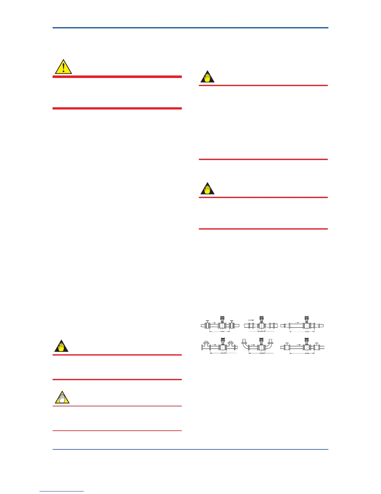
BasedonJISB7554andourpipingconditiontestdata,
we recommend the piping conditions as shown in the
followinggures.
Wheninstallingtwoormoremagneticowmetersona
single pipe, provide a run of at least 10D between them.
Gate valve
fully open
Reducer
pipe
Expander
pipe
Tee
90-degree bent
Various valves
5D or more
2D
or more
2D
or more
2D
or more
10D or more
10D or more
5D or more
5D or more
0 is allowable. 0 is allowable.
0 is allowable.
0 is allowable.
Figure 3.1.1 Required Lengths of Straight Runs
*1: Do not install anything in the vicinity that may interfere
withthemagneticeld,inducedsignalvoltages,orow
velocitydistributionsoftheowmeter.
*2: A straight run may not be required on the downstream
sideoftheowmeter.However,ifadownstreamvalve
orotherttingcausesirregularityordeviationinows,
provide a straight run of 2D to 3D on the downstream side.
*3: The valves shall be mounted on the downstream side so
thatdeviatedowsdonotoccurintheowtubeandto
avoid startup from an empty condition.
 Loading...
