IMPORTANT
When optional code A (lightning protector) is selected,
the ground should satisfy Class C requirements
(groundingresistance,10Ωorless).
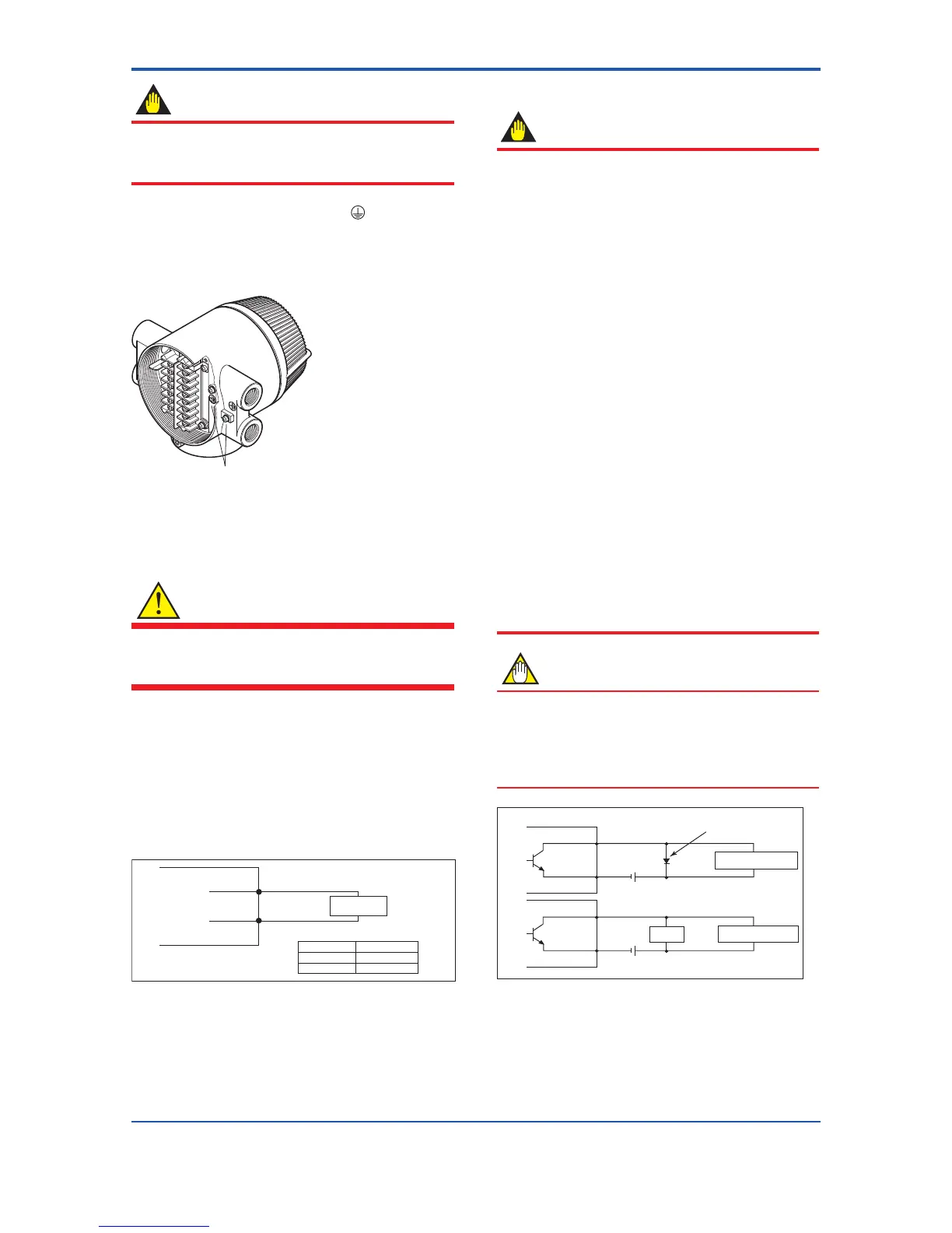
• The protective grounding terminals
are located on
the inside and outside of the terminal area.
Either terminal may be used.
• Use 600 V vinyl insulation wires as the grounding
wires.
Protective grounding terminals
Figure 4.3.9 Protective Grounding Terminal Location for
AXFA14 Remote Converter
(6) Connecting to External Instruments
WARNING
Before wiring with external instruments, be sure to turn
off the power supply for AXFA14 Remote Converter
and any external instruments.
Connect the AXFA14 Remote Converter terminal to
external instruments, giving attention to the following
points.
For F
OUNDATIONeldbusprotocol,refertoIM01E20F02-
01E.
For PROFIBUS PA protocol, refer to IM 01E20F12-01E.
4 to 20 mA DC Current Output
Resistive load max. 750 Ω
Receiver
Instrument
AXFA14
l+
l-
F0442.ai
Communication
Resistive load
BRAIN
HART
250 to 450 Ω
250 to 600 Ω
Figure 4.3.10 4 to 20 mA DC Output Connection
Pulse Output
IMPORTANT
• As this is a transistor contact (insulated type),
give attention to proper voltage and polarity when
wiring.
• Do not apply a voltage larger than 30V DC or
a current larger than 0.2A in order to prevent
damage to the instrument.
• Wheninputlterconstantoftheelectroniccounter
is large in relation to the pulse width, the signal will
decrease and the count will not be accurate.
• If the input impedance of the electronic counter is
large, an induction noise from the power supply
may result in inaccurate counts. Use a shield cable
orsufcientlyreducetheinputimpedanceofthe
electroniccounterwithinthemagneticowmeter
pulseoutputspecicationrange.
• The active pulse output (Optional code EM) cannot
be used in conjunction with the standard pulse
output.
• When the active pulse output (Optional code EM)
is selected, do not be short-circuit between the
DO+ and DO– terminals to avoid damaging the
instrument.
• When the active pulse output (Optional code EM)
is selected, the range of pulse rate must be set to 2
pps maximum.
• To avoid communication (BRAIN/ HART) failure, it
is recommended to use the shield cable.
NOTE
For pulse output from the DO terminals, parameters
mustbeset.Referto“ParameterDescription”inthe
user’s manual of the AXFA14G/C Magnetic Flowmeter
Remote Converter [Hardware Edition/ Software
Edition] (IM 01E20C02-01E).
 Loading...
