App-12
IM DLM3054-01EN
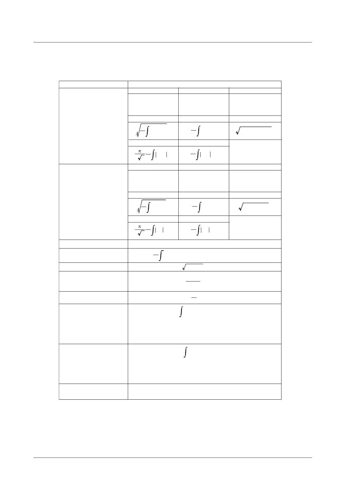
Appendix 5 How Power Measurement Items Are Determined
The power measurement feature is available on models with the /G03 option. The following table shows how the
power measurement items are determined or the equations that are used.
Measurement Item
Methods of Determination and Equation
Maximum U+pk
Minimum U-pk
Amplitude Up-p
True rms value Urms
DC component Udc
AC component Uac
Rectified mean value calibrated
to the rms value Umn
Rectified mean value Urmn
Udc Uac
Umn Urmn
Minimum
(same as waveform
parameter “Min”)
U+pk U−pk
Maximum
(same as waveform
parameter “Max”)
Bandwidth
(same as waveform
parameter “P-P”)
Minimum
(same as waveform
parameter “Min”)
Maximum
(same as waveform
parameter “Max”)
Bandwidth
(same as waveform
parameter “P-P”)
Up-p
Maximum I+pk
Minimum I-pk
Amplitude Ip-p
True rms value Irms
DC component Idc
AC component Iac
Rectified mean value calibrated
to the rms value Imn
Rectified mean value Irmn
Active power P [W]
Reactive power Q [var]
Power factor λ
Watt-hours
[Wh]
Wp
Wp+
Wp-
Abs.Wp
Ampere-hours
[Ah]
q
q+
q-
Abs.q
Average frequency Avg Freq
[Hz]
q is the sum of positive and negative Idc (ampere-hours).
q+ is the sum of positive Idc (ampere-hours).
q- is the sum of negative Idc (ampere-hours).
Abs.q is the sum of q+ and q- (the sum of absolute ampere-hours).
Wp is the sum of positive and negative watt hours.
Wp+ is the sum of positive P (consumed watt-hours).
Wp- is the sum of negative P (watt-hours returned to the power supply).
Abs.Wp is the sum of Wp+ and Wp- (the sum of absolute watt-hours).
Load circuit
Impedance
Z [Ω]
T
1
T
0
u(t) dt
Urms
2
− Udc
2
T
1
T
0
u(t) dt
2
2
T
1
T
0
u(t) dt
Idc Iac
Imn Irmn
T
1
T
0
i(t) dt
Urms
T
1
T
0
u(t)
2
dt
Irms
T
1
T
0
i(t)
2
dt
Irms
2
− Idc
2
T
1
T
0
i(t) dt
2
2
T
1
T
0
i(t) dt
I+pk I−pk
Ip-p
T
1
T
0
u(t)• i(t)dt
Apparent power S [VA]
Urms•Irms
S
2
− P
2
P
S
Urms
Irms
T
0
u(t)• i(t) dt
T
0
i(t) dt
Voltage U [V]
Current I [A]
u(t) • i(t): Instantaneous power
Average frequency
(same as waveform parameter “Avg Freq”)
T: measurement time period, u(t): sampled data of the voltage, i(t): sampled data of the current
Appendix
 Loading...


