4-29
IM DLM3054-01EN
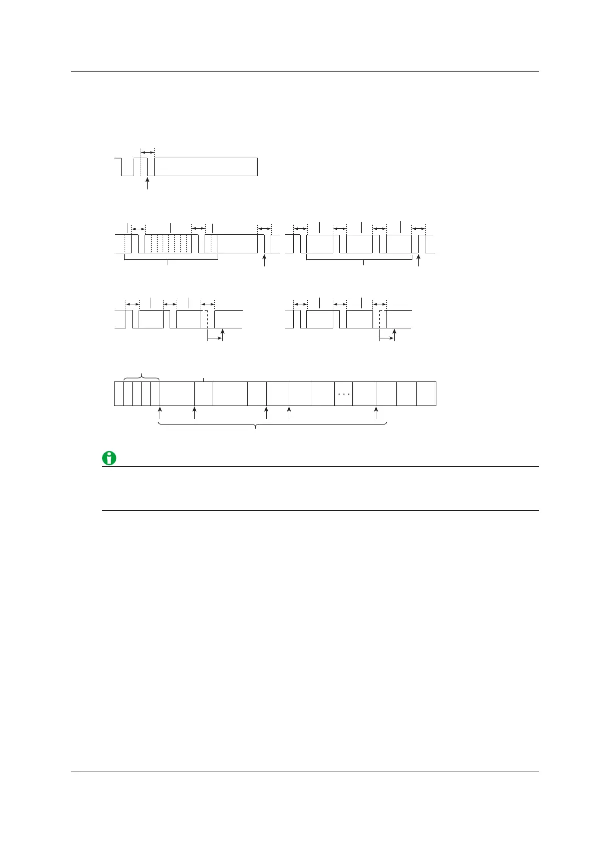
Trigger Point
The trigger occurs near the BSS falling edge immediately after all the trigger conditions are met. The only
exception is that the trigger occurs near the FES rising edge when the trigger mode is set to Error, there is no
CRC error in the FlexRay bus signal header, and there is only a CRC error in the frame.
Header Segment
BSS
BSS: Byte Start Sequence
FES: Frame End Sequence
TSS
F
S
S
BSS
BSS
BSS
Cycle
Count
8 bits
1 bit 8 bits 2 bits
8 bits 8 bits
BSS BSS BSS
FES
Header CRC
Frame CRC
• When there is a CRC error in the frame
Triggers here
8 bits 8 bits
BSS BSS FES
Error mode
• When there is a CRC error in the header
• When there is an FES error
Triggers here
Triggers here
Triggers here
Approx. 2 bits
8 bits 8 bits
BSS BSS BSS
• When there is a BSS error
Triggers here
Approx. 2 bits
Example: Error at 00
Example:
Error at 00
Frame ID
Payload Length
Header
CRC
Cycle
Count
Data 0 Data 1
Data 2
Data n
CRC CRC
CRC
Frame Indicator
1
1
1 1 1
. . . . .
When the trigger mode is set to Error, the instrument uses its internal sampling clock for sampling, so jitter
equal to one period of the sampling clock arises. One period of the sampling clock is a period of time equal to
1/8 of the bit width at the specified bit rate. For example, when the bit rate is 5 Mbps, the jitter is 25 ns.
4 Triggering
 Loading...


