4-61
IM DLM3054-01EN
• Status and Communication
Select the method of detecting error type Status and Communication. Select bit 0 or bit 1 or both. If you select
both, errors are detected on the OR condition.
Bit 0: Bit 0 becoming 1 is detected as an error.
Bit 1: Bit 1 becoming 1 is detected as an error.
Source (Source)
Source (Source)
Set the trigger source to one of the settings below. If you select LOGIC, select the source bit.
CH1 to CH4, LOGIC (Bit 0 to Bit 7)
Level (Level), HF Rejection (HF Rejection), Noise Rejection (Noise Rejection)*
Set these items for the trigger source.
These items are the same as those of the edge trigger.*
* You can set this only when the trigger source is set to LOGIC and the 701989 logic probe is connected.
Hysteresis (Hysteresis)
You can set this only when the trigger source is CH1 to CH4.
This item is the same as that of the CAN bus trigger.
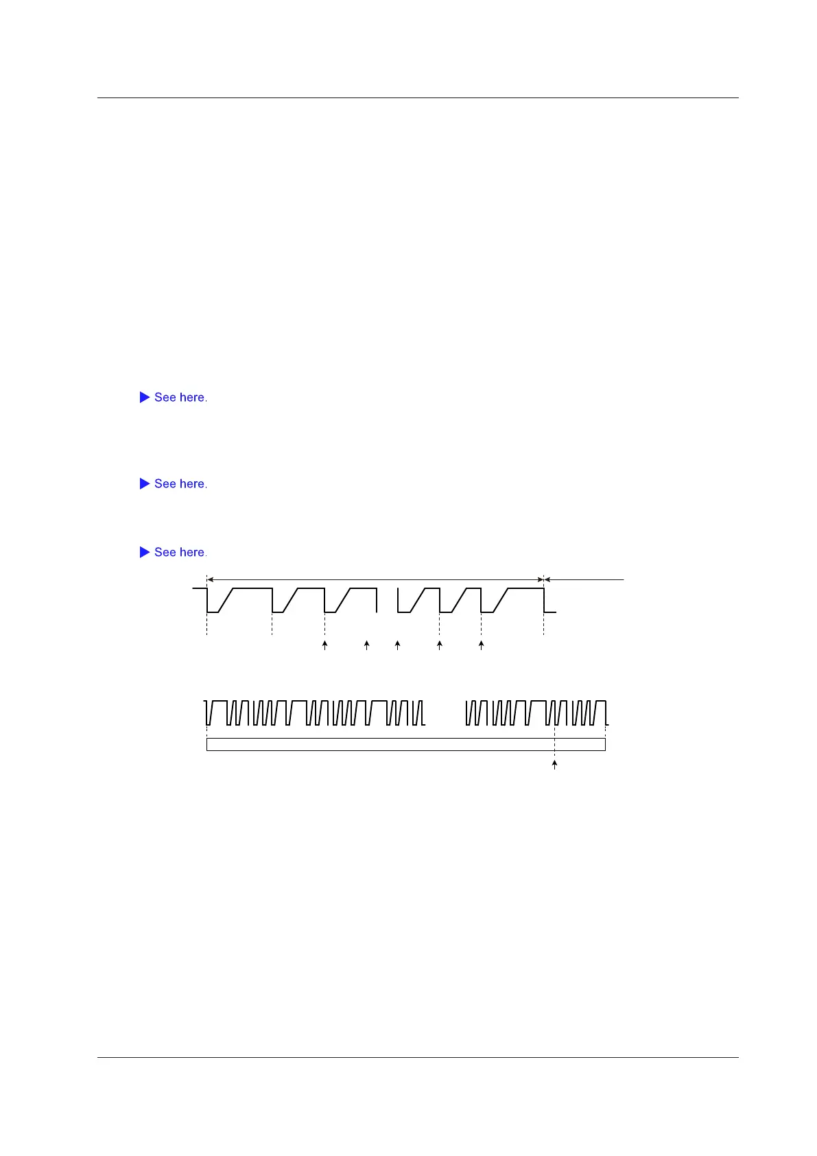
Trigger Point
The following figures illustrate the trigger points. For other trigger points, see appendix 6.
………
………
… … … … …
Message 1 Message 2 Message N
ID, Data, CRC
S&C
(1)(2)(6)
(7)(9)
(3)(7)(7) (7)
(7)(8)
…
SYNC/CAL CRC Pause
Message (Frame)
Next message
(Frame)
Status and
Communication
Data Nibbles: 1 to 6
(1 nibble: 4 bits)
Positions (1) to (10) above are trigger points for the following conditions.
(1) Every Fast CH
(2) Fast CH S&C
(3) Fast CH Data
(4) Every Slow CH
(5) Slow CH ID/Data
(6) Successive CAL Pulses Error, detection method Option 2
(7) Nibble Data Value Error
(8) Fast CH CRC Error
(9) Status and Communication Error
(10) Slow CH CRC Error
4 Triggering
 Loading...


