<4.InstallingImpulsePiping>
26
IM01C25A01-01E
F0408.ai
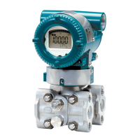
Liquid
Gas Steam
Union or flange
Tee
Tee
Drain plug
Drain valve
Drain valve
Drain plug
Union or flange
Union or
flange
Union or flange
Tap valve
Tap valve
Tee
Drain valve
Drain plug
Tap valve
Figure4.8 ImpulsePipingConnectionExamples
(forgauge/absolutepressure
transmitters)
4.3 ProcessPipingInstallation
Precautions(EJ115)
4.3.1 ConnectingProcessPipingtothe
Transmitter
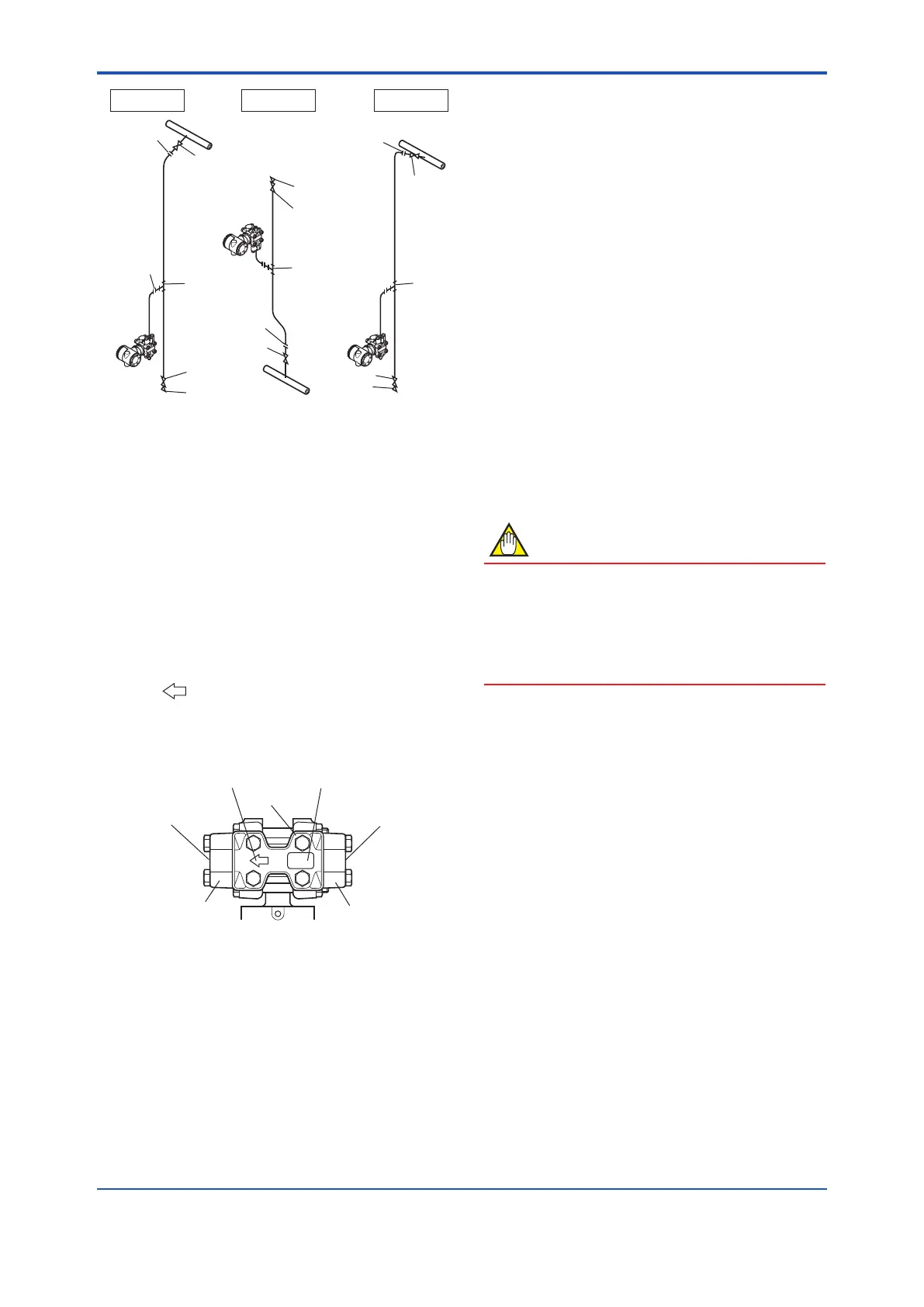
(1) ConrmingtheProcessFluidFlow
Direction
Themark“ ”onthemanifoldindicatesthedirectionin
whichtheprocessuidisowed(fromrighttoleft).
Whenconnectingtheprocesspipingtotheprocess
connector,conrmtheprocessuidowdirection.
F0409.ai
Flow direction (from right to left)
Manifold
Orifice name plate
Process connector
(low pressure side)
Process connector
(high pressure side)
Process connection
(outflow side)
Process connection
(inflow side)
Figure4.9 ManifoldandFlowDirectionIndication
(2) TighteningtheProcessConnector
MountingBolts
Thetransmitterisshippedwiththeprocessconnector
mountingboltsonlylooselytightened.Afterconnecting
theprocesspiping,tightentheseboltsuniformlyto
preventleakswithatorqueof39to49N·m{4to5kgf·m}.
(3) RemovingtheProcessConnectorPort
DustproofCap
Theprocessconnectorportthreadsarecoveredwitha
plasticcaptoexcludedust.Thiscapmustberemoved
beforeconnectingthepiping.(Becarefulnottodamage
thethreadswhenremovingthiscap.Neverinserta
screwdriverorothertoolbetweenthecapandport
threadstoremovethecap.)
4.3.2 RoutingtheProcessPiping
(1) RelationshipbetweenProcessFluid
andManifoldLocations(Forthevertical
impulsepipingtype)
Ifcondensate(orgas)generatedintheprocesspiping
wereallowedtoaccumulate,thenitwouldbenecessary
toremoveitperiodicallybyopeningthedrain(or
vent)plug.However,thiswouldgenerateatransient
disturbanceinthepressuremeasurement.Therefore,the
processpipingmustberoutedsothatanycondensate(or
gas)generatedintheprocesspipingwillnotaccumulate
inthepressure-sensingassemblyofthetransmitter.
NOTE
• Iftheprocessuidisagas,thenasarulethe
manifoldmustbelocatedatthedownsideofthe
pressure-sensingassembly.
• Iftheprocessuidisaliquid,thenasarulethe
manifoldmustbelocatedattheupsideofthe
pressure-sensingassembly.
(2) PipeSizeforProcessPiping
Usea15mm(1/2-inch)pipeforprocesspiping
connectiontotheprocessconnector.
(3) PreventingFreezing
Ifthereisanyriskthattheprocessuidinthetransmitter
pressure-sensingassemblycouldfreezeorsolidify,use
asteamjacketorheatertomaintainthetemperatureof
theuid.
(4) ProcessPipingConnectionExamples
Figure4.10showsexamplesoftypicalprocesspiping
connections.Beforeconnectingthetransmittertothe
process,studythetransmitterinstallationlocation,the
processpipinglayout,andthecharacteristicsofthe
processuid(corrosiveness,toxicity,ammability,etc.),in
ordertomakeappropriatechangesandadditionstothe
connectioncongurations.
Notethefollowingpointswhenreferringtothesepiping
examples.
• Theprocesspipingmaterialusedmustbecompatible
withtheprocesspressure,temperature,andother
conditions.
 Loading...


