<5.Wiring>
32
IM01C25A01-01E
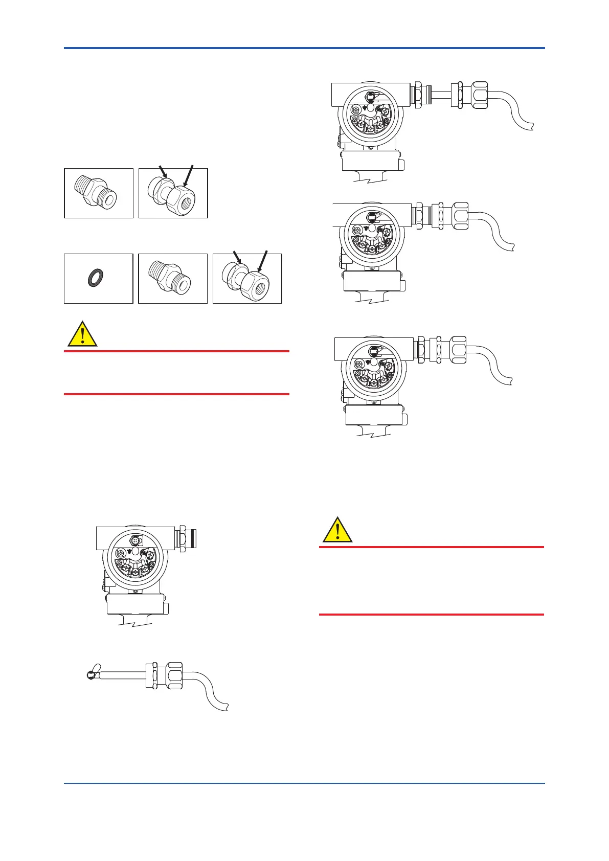
• Componentsforthecablegland
Thecableglandassemblyconsistsofanentry,seal,
runningcoupler,andbacknut.Conrmthatthesealis
attachedinsidetheentryandthatthethreadsizeofthe
cableglandisthesameasthatfortheRTDelectrical
connection.
F0516.ai
M20 Type
Gasket
Entry with Seal
Running
Coupler
Backnut
Entry with Seal
Running
Coupler
CAUTION
Input/outputsignalisnon-isolated.
Donotturnonpowersupplyuntilyoucompleteallthe
wiringwork.
Procedure
(1)Disassemblethecablegland:loosentherunning
couplertoseparatethebacknutfromtheentry.
(2)Removetheprotectioncapoverthetransmitter
electricalconnectionandinstalltheentryonthe
electricalconnection.Notethatanon-hardening
sealantshouldbeappliedtothethreadsfora1/2NPT
connectionandagasketshouldbeusedforanM20
connection.
Y L P P U S
E S L U P
K C E
H C
M R
A
L
A
F0517.ai
(3)PasstheRTDcablethroughtherunningcouplerand
backnutassembly.
F0518.ai
(4)InserttheRTDcableandrmlyplugitsconnectorinto
theconnectingportinthetransmitter'sterminalbox.
Y L P P U S
E S L
U P
K
C E
H C
M R
A
L A
F0519.ai
(5)Aligntherunningcouplerontheentry.
Y L P P U S
E S L
U P
K
C E
H C
M R
A
L A
F0520.ai
(6)Turntherunningcoupleruntilthesealintheentry
comesintocontactwiththeRTDcable.
Y L P P U S
E S L
U P
K
C E
H C
M R
A
L A
F0521.ai
(7)Rotatetherunningcoupleranotherhalfturnto
securelytightenthesealontheRTDcable.
(8)Useaprotectionconduit,ifnecessary.
Inthiscase,insertthecablethroughtheconduitand
attachittotheBacknut.
CAUTION
Afterthecableissecuredasexplainedabove,donot
tightentherunningcoupleranyfurther;todosocould
damagetheRTDconnection.
Donotpullthecableorsubjectittoexcessive
mechanicalshock.

 Loading...


