Stamp Company : Stamp Certification Institute :
Signature : Remarks :
Model EXA SC202S-F
Model EXA SC202S-B
Model EXA SC202S-P
Model EXA SC202S-D
Title : Installation Drawing SC202S CSA
Number : FF1-SC202S-00 Page : 4 of 10
Revision : 2.4
YOKOGAWA EUROPE B.V.
Date : 26/07/2004
〈 Sensor(s) are a thermocouple, RTD’s, passive resistive switch devices, or is CSA entity
approved and meet connection requirements.
〈 Electrical data of the EXA SC202S-F & SC202S-P :
- Supply and output circ uit::
Maximum input voltage Vmax=24 V or Maximum input voltage Vmax=17.5 V
Maximum input current Imax=250 mA Maximum input current Imax=380 mA
Maximum input power Pmax=1.2 W Maximum input power Pmax=5.32 W
Effective internal capacitance Ci=737 pF; E ffective internal inductance Li=2.6 µH.
- Sensor input circuit:
Maximum output voltage Voc=14.4V; Maximum output current Isc=12.8 mA
Maximum allowed external capacitance Ca=103 nF
Maximum allowed external inductance La=200 mH
〈 Any CSA approved I.S. interface may be used that meets the following requirements:
Vmax
≤ 24 V or Vmax ≤ 17.5 V
Imax
≤ 250 mA Imax ≤ 380mA
Pmax
≤ 1.2 W Pmax ≤ 5.32 W
Ca ? 737 pF + Ccable; La ? 2.6 µH + Lcable
Installation should be in accordance with Canadian Electrical Code, Par t I or CEC, Part I.
Maximum safe area voltage should not exceed 250 Vrms.
For Class I, Div. 2, Group ABCD the CSA approved I.S. interface is not required,
and the sensor input circuit is non -incendive having the parameters:
Maximum output voltage Voc=14. 4V; Maximum output current Isc=12.8 mA
Maximum allowed external capacitance Ca=1.4 µF
Maximum allowed external inductance La=900 mH
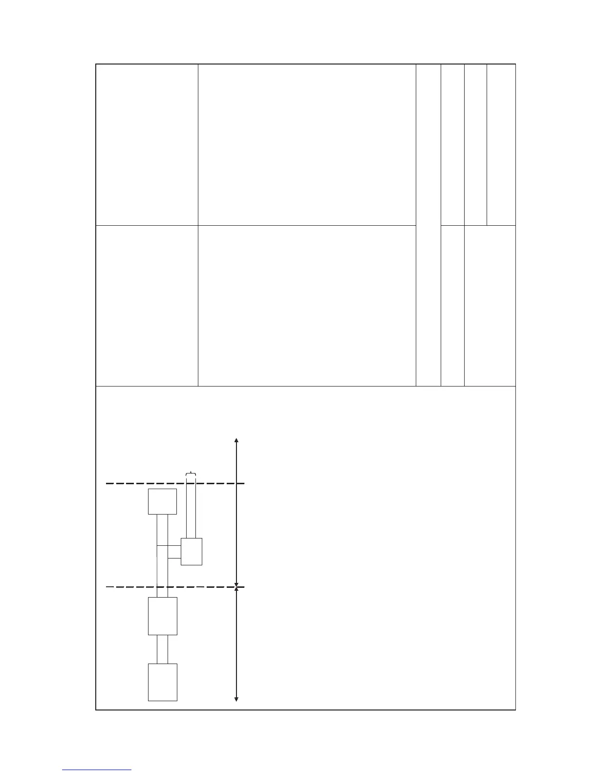
Safe area
Hazardous area
Zone 1
Zone 0 or 1
Safe area
Apparatus
I.S.
interface
I.S.
certified
Terminator
EXA
SC202S-F
& SC202S-P
Sensor
Connections
V
ma
x
= 24 V or V
max
= 17,5 V
I
max
= 250 mA I
max
= 380 mA
P
ma
x
= 1,2 W P
max
= 5,32 W
CSA Ex ia Cl ass I, DIV. 1, Group ABCD
T4 for ambient temp.
≤ 55 ϒC
T6 for ambient tem

 Loading...