Stamp Company : Stamp Certification Institute :
Signature : Remarks :
Model EXA SC202S-A
No revision to drawing without prior
FM Approval
Title : FM Control Drawing SC202S-A (Intrinsic Safety)
Number : FF1-SC202S-00 Page : 5 of 10
Revision : 2.4
Sensor
terminals 11-16
Max. cablelength: 60 mtr.
Cable dia. : 3 12 mm.
Sensor
terminals 11-16
Max. cablelength: 60 mtr.
Cable dia.: 3 12 mm.
n classified Location
FM Approved
Power Supply
(HART compatible)
Output
Supply
+
_
G
Classified Location
Unclassified Location
+
_
G
Protective
earth
Protective
earth
Intrinsically safe design
FM Class I, Div.1, Group ABCD, T4 for ambient temp. < 55¡C
T6 for ambient temp. < 40¡C
EXA SC202S analyser
+
-
Load
Resistance
Classified Location
Protective
earth
+
_
24 volts DC Nominal
Supply Voltage.
FM Approved safety barrier or
power supply
with Rint = 300
Ω
(HART compatible)
For electrical data:
see text below.
For electrical data:
see text below.
Intrinsically safe design
FM Class I, Div.1, Group ABCD, T4 for ambient temp. < 55¡C
T6 for ambient temp. < 40¡C
EXA SC202S analyser
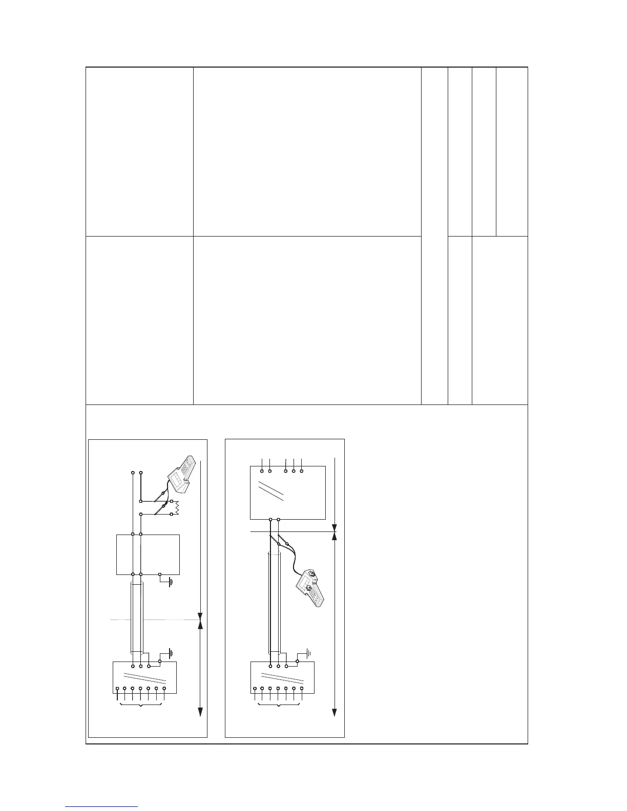
Figure 1
Figure 2
• Electrical data of the EXA SC202S :
- Supply circuit (terminals + and -): - Sensor input circuit (terminals 11 through 16):
Maximum input voltage V
max
= 31.5 V. Maximum output voltage V
t
= 14.4 V.
Maximum input current I
max
= 100 mA. Maximum output current I
t
= 12.8 mA.
Maximum input power P
i
= 1.2 W. Maximum allowed external capacitance C
a
= 103 nF.
Effective internal capacitance C
i
= 22 nF. Maximum allowed external inductance L
a
= 200 mH.
Effective internal inductance L
i
= 22 µH.
• If Hand Held Terminal (HHT) is not connected to the power supply lines of the EXA SC202S (see figure 1):
Any FM Approved barrier or power supply may be used that meets the following requirements.
V
oc
or V
t
≤ 31.5 V; I
sc
or I
t
≤ 100 mA; C
a
≥ 22nF + C
cable
; L
a
≥ 22µH + L
cable
If HHT is connected to the power supply lines of the EXA SC202S (see figure 2):
The Hand Held Terminal must be FM Approved. Refer to the manufacturers control drawing of the HHT and the barrier/power
supply to determine the cable parameters.
(V
oc
or V
t
) + V
HHT
≤ 31.5 V; (I
sc
or I
t
) + I
HHT
≤ 100 mA; C
a
≥ 22nF + C
cable
+ C
HHT
; L
a
≥ 22µH + L
cable
+ L
HHT
When installing this equipment, follow the manufacturer s installation drawing.
Installation should be in accordance with ANSI/ISA RP 12.06.01 Installation of Intrinsically Safe Systems for Hazardous
(Classified) Locations and the National Electrical Code (ANSI/NFPA 70).
Control equipment connected to the barrier/power supply must not use or generate more than 250 Vrms
or Vdc.
• Resistance between Intrinsically Safe Ground and earth ground must be less than 1.0 Ohm.
WARNING
- Substitution of components may impair Intrinsic Safety
- To prevent ignition of flammable or combustible atmospheres, disconnect power before servicing or read, understand
and adhere to the manufacturer s live maintenance procedures.
YOKOGAWA EUROPE B.V.
Date : 26/07/2004

 Loading...