Stamp Company : Stamp Certification Institute :
Signature : Remarks :
Model EXA SC202S-F
Model EXA SC202S-P
No revision to drawing without prior
FM Approval
Title : FM Control Drawing SC202S-F & SC202S-P (Intrinsic safe Entity
concept)
Number : FF1-SC202S-00 Page : 8 of 10
Revision : 2.4
YOKOGAWA EUROPE B.V.
Date : 26/07/2004
〈 Sensor(s) are of a passive type to be regarded as ’simple apparatus’, devices which
neither store nor generate voltages over 1. 5 V, currents over 0.1 A, power over 25 mW or
energy over 20
µJ, or are FM Approvals entity approved and meet connection
requirements.
〈 Electrical data of the EXA SC202S-F & SC202S-P :
- Supply circuit:
Maximum input voltage Vmax=24 V
Maximum input current Imax=250 mA
Maximum input power Pi=1.2 W
Effective internal capacitance Ci=73 7 pF; Effective internal inductance Li=2.6
µH.
- Sensor input circuit:
Maximum output voltage Vt=14.4 V; Maximum output current It= 12.8 mA
Maximum allowed external capacitance Ca= 103 nF
Maximum allowed external inductance La= 200 mH
〈 Any FM Approved barrier may be used that meets the following requirements:
Voc or Vt
≤ 24 V
Ioc or It
≤ 250 mA
Poc or Pt
≤ 1.2 W
Ca
? 737 pF + Ccable; La ? 2.6 µH + Lcable
When installing this equipment, follow the manufacturer s installation drawing.
Installation should be in accordance with ANSI/ISA RP 12.06.01 Installation of Intrinsically
Safe Systems for Hazardous (Classified) Locations and the National Electrical Code
(ANSI/NFPA 70).
Associated apparatus connected to the barrier must not use or generate more than
250 Vrms
or Vdc.
〈 Resistance between Intrinsically Safe Ground and earth ground must be less than 1.0
Ohm.
WARNING
- Substitution of components may impair Intrinsic Safety
- To prevent ignition of flammable or combustible atmospheres, disconnect power
before servicing or read, understand and adhere to the manufacturer s live
maintenance procedures.
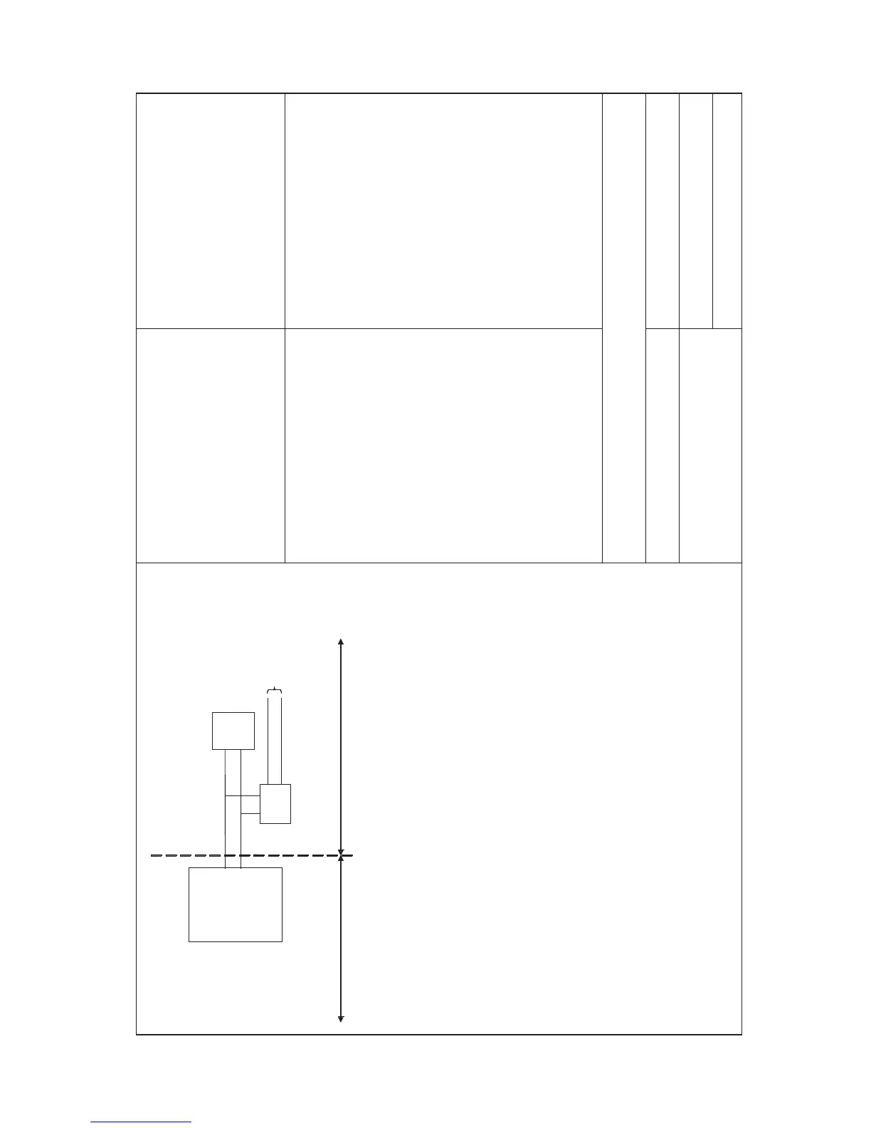
Unclassified Location
Classified Location
Division 1
FM Approved
barrier
Voc (Vt) ¡Ü24 V
Ioc (It)
¡Ü 250 mA
Poc (Pt)
¡Ü 1,2 W
Ca
¡Y 737pF+ Ccable
La
¡Y 2,6 H + Lcable
I.S.
certified
Terminator
EXA
SC202S-F &
SC202S-P
Sensor
Connections
Max. cablelength: 60 mtr.
Cable dia. : 3 1 2 mm.
FM Class I, DIV. 1, Group ABCD
T4 for ambient temp.
≤ 55 ϒC
T6 for ambient tem

 Loading...