Stamp Company : Stamp Certification Institute :
Signature : Remarks :
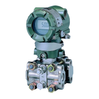
Model EXA SC202S-B
Model EXA SC202S-D
No revision to drawing without prior
FM Approval
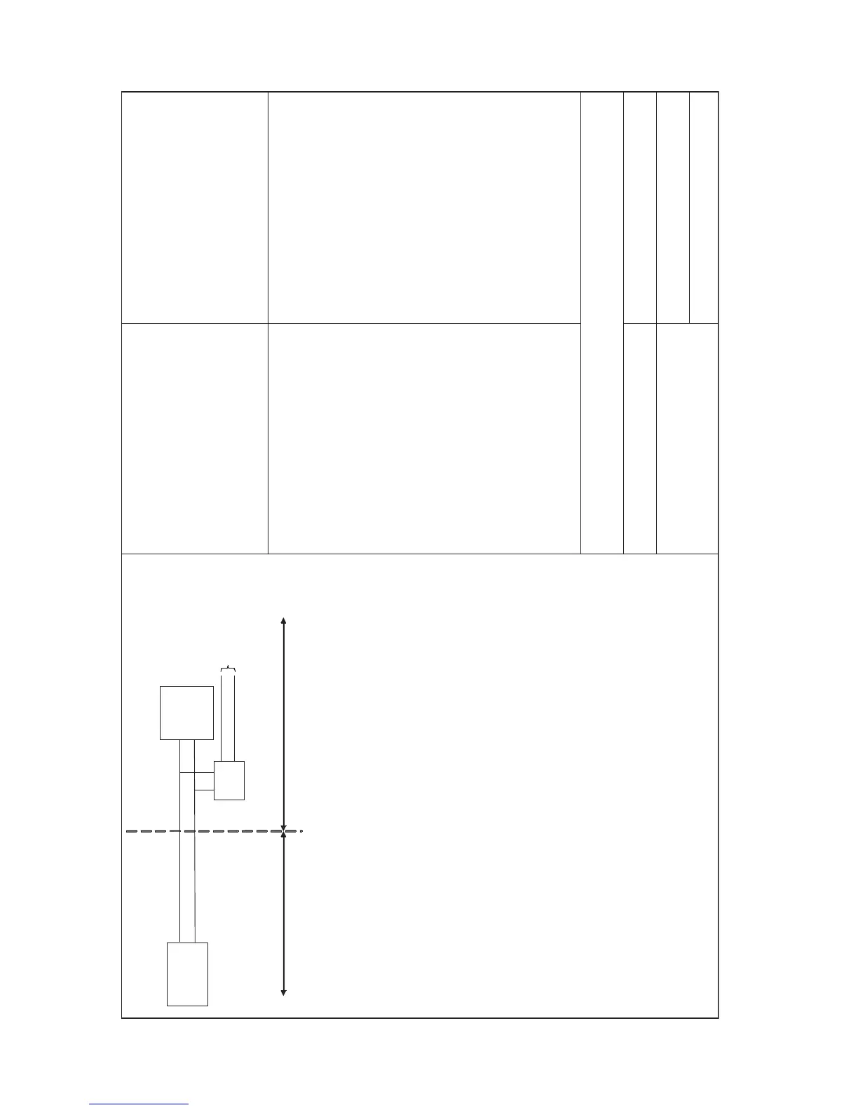
Title : FM Control Drawing SC202S-B & SC202S-D (Non-incendive Entity
concept)
Number : FF1-SC202S-00 Page : 10 of 10
Revision : 2.4
YOKOGAWA EUROPE B.V.
Date : 26/07/2004
〈 Sensor(s) are of a passive type to be regarded as ’simple apparatus’, devices which neither store nor
generate voltages over 1.5 V, currents over 0.1 A, power over 25 mW or energy over 20 µJ, or are FM
Approvals entity approved and meet connection requirements.
〈 Electrical data of the EXA SC202S -B & SC202S-D:
- Supply circuit: Vmax=32 V; Pi=1.2 W; Ci= 737 pF; Li= 2.6 H
- Sensor input circuit: Vt=14.4 V; It=12.8 mA; Ca=1.4 F; La=900 mH
When installing this equipment, fol low the manufacturers installation drawing.
Installation shall be in accordance with Article 501.4(B) of the National Electrical Code (ANSI/NFPA 79).
Nonincendive field wiring may be installed in accordance with Article 501.4(B)(3)
〈 Grounding shall be in accordance with Article 250 of the National Electrical code.
WARNING
- Substitution of components may impair suitability for Division 2.
- Do not remove or replace while circuit is live unless area is know to be non -hazardous
- Explosion Hazard — Do not disconn ect equipment unless area is know to be non -hazardous
- Do not reset circuit breaker unless power has been removed from the equipment or the area is know to be non -
hazardous
Unclassified Location
Classified Location
Division 2
FM Approved
Power Supply
Voc
¡Ü 32 VDC
FM Approved
Terminator
R = 90..100
C = 0..2,2 F
EXA
SC202S-B &
SC202S-D
Sensor
Connections
Max. cablelength: 60 mtr.
Cable dia.: 3 12 mm.
FM Class I, DIV. 2, Group ABCD
T4 for ambient temp.
≤ 55 ϒC
T6 for ambient tem

 Loading...