FORM 100.50-NOM7 (808)
71
JOHNSON CONTROLS
6
The controller will wait 30 seconds from the time of the
above control actions and then restart the Supply Fan
by setting the Supply Fan output to ON (high). Normal
heating or cooling operation will begin.
VFD Bypass operation will continue until the VFD By-
pass input goes low (0 volts). The unit will then return
to normal operation.
ANALOG INPUT OPERATION
This section describes the control operation of the (13)
thirteen analog inputs. These inputs will be used by the
control to monitor and respond to unit temperatures,
pressures, enthalpy, etc. The connection “layout” for the
IO (inputs/outputs) is shown in the MOD-DCU connec-
tion map in Figure 20. Notice that the gure shows the
Jack connection designated by “J”, and the pin number
located on the inside of the board diagram. The input
or output designations are shown on the outside of the
gure. For example, J11 – 1 is jack eleven - pin 1 and
is AI5 (analog input 5). J13 – 3 is jack 13 - pin 3 and is
AI14 (analog input 14). For example, AI5 (J11 – 1) is the
input for Outside Air Relative Humidity, and is used as
part of the economizer control scheme. AI13 (J13 – 1)
is the input for Supply Air Temperature, and is used for
control in both the CV and VAV control schemes. The
analog inputs are also in the I/O tables in Table 17 with
descriptions for each input.
Return, Outside, Supply Air and Slab
Temperature
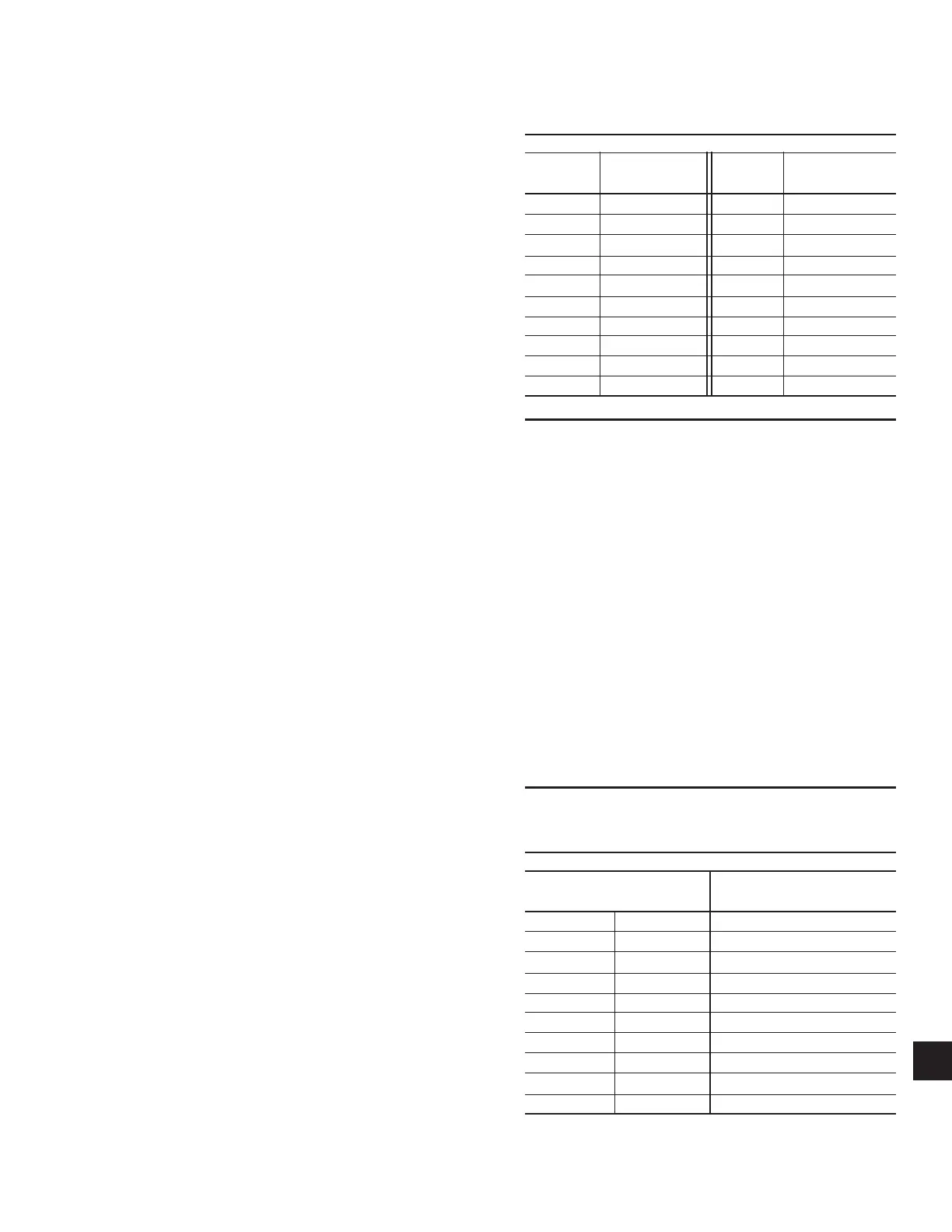
The temperature sensors are RTD sensors that can be
checked with an ohmmeter. Table 8 provides the resis-
tance values for a given temperature in °F.
Duct Pressure Transducer
The duct pressure transducer is mounted in the return air
section of the unit on the panel wall. The purpose of this
transducer is to sense and convert the static pressure in the
supply-side of the duct to a DC voltage. The DC voltage
is then sent to the unit controller and compare against the
Duct Static Pressure setpoint. The control wiring is fac-
tory wired, but pneumatic tubing must be eld supplied
and installed (refer to Installation section in manual).
The duct pressure transducer measures dierential pres-
sure between the pressure in the duct and atmospheric
pressure. When verifying transducer operation, the
technician must insert a tee into the pneumatic tubing
to connect a manometer and verify the pressure being
applied to the transducer. Once this pressure is known,
a comparison can be made of the duct pressure vs. out-
put volts DC from the transducer. Table 11 shows the
relationship between the pressure applied to the duct
pressure transducer and the output voltage.
Building Pressure Transducer
The building pressure transducer is located in the return
air section of the unit. The purpose of this transducer is
to sense and convert the static pressure in the building
to a DC voltage. The DC voltage is then sent to the unit
controller and compare against the Building Pressure
setpoint. The control wiring from the transducer is fac-
tory wired, but pneumatic tubing must be eld supplied
and installed (refer to Installation section in manual).
The building pressure transducer measures dierential
pressure between the pressure in the building and at-
mospheric pressure. When verifying transducer opera-
TABLE 8 – TEMPERATURE SENSOR RESISTANCE
TABLE
TEMPERATURE SENSOR OUTPUT TABLE
TEMP. OHMS TEMP. OHMS
°F RESISTANCE °F RESISTANCE
-20 751 80 1030
-10 777 90 1060
0 803 100 1090
10 830 110 1121
20 858 120 1152
30 885 130 1184
40 914 140 1216
50 942 150 1248
60 971 160 1281
70 1000 170 1314
TABLE 9 – *DUCT PRESSURE TRANSDUCER
OUTPUT TABLE
DUCT PRESSURE TRANSDUCER OUTPUT TABLE
DIFFERENTIAL INPUT OUTPUT VOLTAGE
PRESSURE - IWG - VDC
0.5 0.25 0.5
1.0 0.50 1.0
1.5 0.75 1.5
2.0 1.00 2.0
2.5 1.25 2.5
3.0 1.50 3.0
3.5 1.75 3.5
4.0 2.00 4.0
4.5 2.25 4.5
5.0 2.50 5.0
* 2.5 IWC Duct Transducer Available for FlexSys Option

 Loading...