furnished with the switch).
The Flow Switch MUST NOT be used to start and stop the unit (i.e. starting and
stopping the chilled water pump). It is intended only as a safety switch.
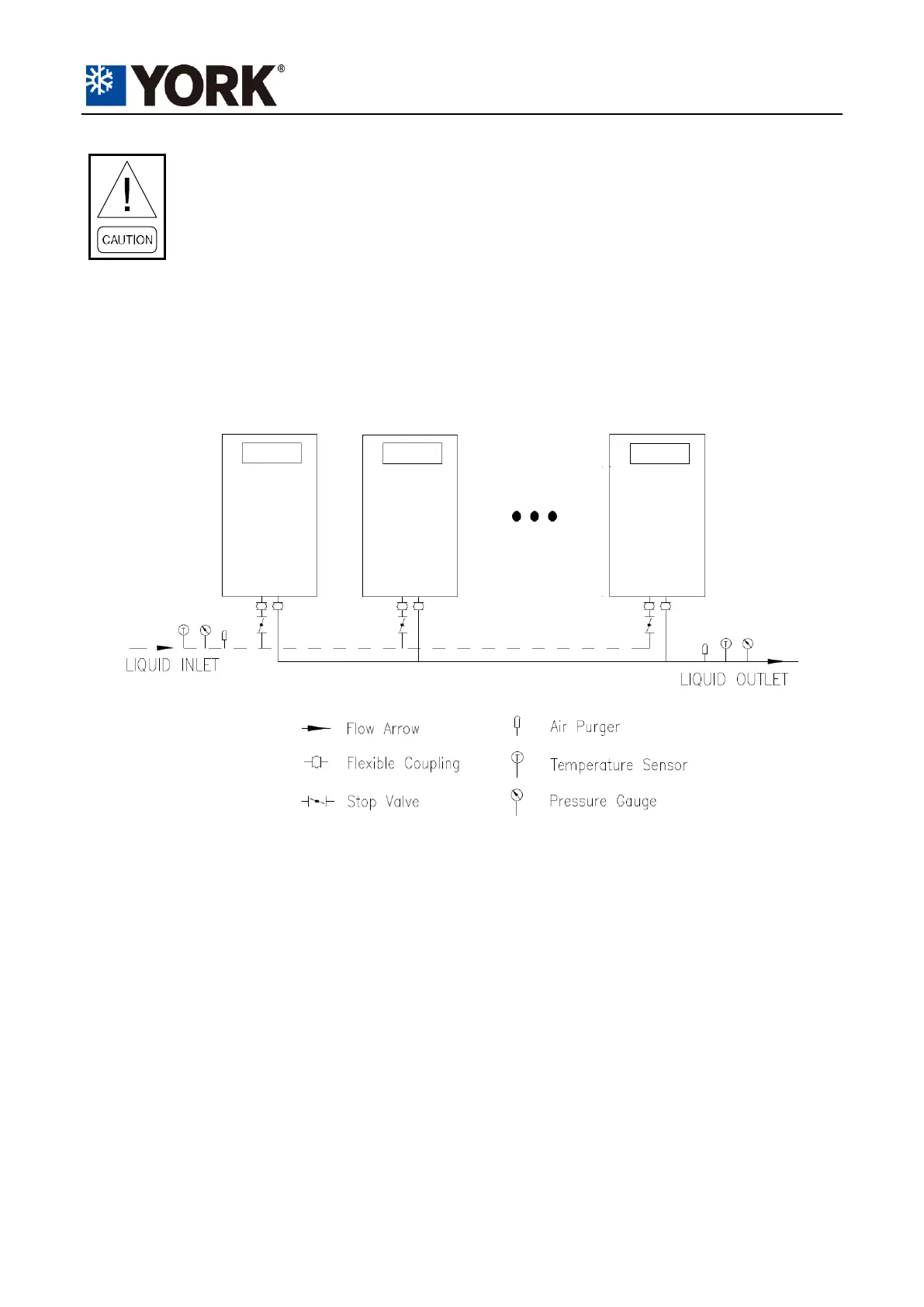
PIPEWORK ARRANGEMENT
The units are able to be connected in a pipe network for centralized control. The control system is
designed to work effectively within a maximum of 32 control boards (communication addresses)
connected. Follow the arrangements below for combinations.
Notes
1. Placement on a level surface free of obstructions (including snow, for winter operation) or air
recirculation ensures rated performance, reliable operation and ease of maintenance.
2. Site restrictions may compromise minimum clearances indicated below, resulting in unpredictable
air flow patterns and possible diminished performance. York's unit controls will optimize operation
without nuisance high pressure safety cutout; however, the system designer must consider potential
performance degradation.
3. The distances between the walls and peripheral units should employ the same rules as shown in
Dimensions section, if the units are surrounded by walls
4. No more than one adjacent wall may be higher than the unit.
5. Installing contractor must include vent and drain accommodations in chilled water piping near the
Cooke Industries - Phone: +64 9 579 2185 Email: sales@cookeindustries.co.nz Web: www.cookeindustries.co.nz