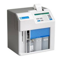
2-3
The
Buffer Pump
draws buffer from its bottle, pumps it through the Sipper Pump body and the
Sipper, and flushes the Sample Chamber.
The
Calibrator Pump
draws the appropriate standard solution from the Calibrator Bottle and
fills the Calibrator Well in the Sample Chamber.
The
Sipper Pump
retracts its piston to draw in standard from the Calibrator Well or sample
from a tube or container. It extends its piston to dispense standard or sample into the Sample
Chamber.
The
Sipper Arm and Sipper Assembly
is raised or lowered by one motor, and moved
horizontally to its various positions by another motor. The positions are: Calibrator Well
(Station #1), Sample Chamber ("home"), Test Tube Holder Station (Station #2), Manual Station
(Station #3), Turntable Station (Station #4) and Monitor Station (Station #5). The Sipper
capacitively senses fluid to control immersion depth and detect errors.
The
Stir Bar
is a plastic encapsulated magnet. It is activated by a motor housed below the
Sample Chamber. It provides thorough mixing inside the chamber.
The
Buffer, Waste
and
Calibrator Bottles
are visible through the front door window for easy
monitoring of fluid levels. A stainless steel shaft projecting into each bottle terminates with a
connector on the lid, providing a signal used to halt operations when the Buffer or Calibrator
Bottles are empty, or when the Waste bottle is full.
The
Sample Chamber
is made of clear acrylic plastic. White and black holders for the sensor
probes are screwed to either side. The immobilized enzyme membranes on the sensor probes
are mounted on O-rings which act as fluid seals on each side of the Sample Chamber. A
reference or auxiliary electrode is housed in the temperature probe and positioned at the back of
the Sample Chamber. It is held in place by a retainer that threads directly into the Sample
Block. A small black O-ring slips over the temperature probe/electrode to provide the seal. The
Calibrator Well is located behind and to the right of the Sample Chamber entry port.
The
Test Tube Holder
pivots out to allow insertion or removal of several common size test
tubes.
The
Display
is a 2 line by 40 character liquid crystal display.
The
Printer
provides a hard copy record of sample results, calibration currents and errors. It
uses 2 1/4 inch (56 mm) wide thermal paper.
The
Keypad
is a 20 key membrane switch. It has 0-9 numeric keys, SPACE and BACK keys
and 8 function keys.
The
Reset Switch
is located on the back of the instrument. It is used to hard reset the operating
system.
The
Remote Communication Port
is an RS-232 serial port. It is used to interface with host
computers or other laboratory instruments.
The
Auxiliary Port
is an interface connector for use with accessories like the YSI 2710
Turntable.

 Loading...