iv
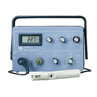
Figure 2.1 Inside Front View of the 2700 SELECT 2-2
Figure 2.2 Back View of the 2700 SELECT 2-4
Figure 2.3 Bottles and Level Sensor Cables 2-5
Figure 2.4 Sample Chamber/Sensors 2-6
Figure 2.5 Enzyme Membrane Installation 2-7
Figure 2.6 Line Voltage Selector 2-8
Figure 2.7 Sipper Adjustment Position 2-10
Figure 3.1 2700 SELECT Software Structure 3-1
Figure 3.2 Sampling Stations 3-4
Figure 3.3 The Test Tube Holder Pivoted Out 3-4
Figure 3.4 The Manual Station 3-6
Figure 5.1 2700 SELECT Software Structure 5-1
Figure 5.2 YSI 2700 SELECT Menu Flow Chart 5-2
Figure 5.3 2700 SELECT Major Components 5-17
Figure 6.1 Sensor Probe and Enzyme Membrane 6-1
Figure 6.2 2700 SELECT Fluid System 6-3
Figure 6.3 Typical Sensor Response 6-4
Figure 6.4 Aging Membrane Response 6-5
Figure 6.5 2700 SELECT Software Structure 6-7
Figure 7.1 Sample Chamber Illustration 7-5
Figure 7.2 Tubing Connections 7-7
Figure 7.3 Pump Tubing installation 7-8
Figure 7.4 Pump Assembly 7-9
Figure 7.5 Fuse Replacement 7-10
Figure 7.6 Sipper Pump Head Removal 7-11
Figure 7.7 Sipper Pump Seal Replacement 7-12
Figure 7.8 Sipper Pump Plunger Position 7-12
Figure 7.9 Sipper Mechanism Drive Screw and Guide Rods 7-13
Figure 9.1 RS-232 Signal Description and Direction 9-1
Figure 9.2 Full Handshaking DTE Interface 9-2
Figure 9.3 Three Wire DTE Interface 9-2
Figure 9.4 2700 SELECT Data Report Format 9-7
Figure 9.5 Report Format Field Information 9-8
Figure 9.6 RM Command Report Format 9-15
Figure 9.7 RI Command Report Format 9-16
Figure G.1 Line Power Cord and Plug Wiring G-1