4
Fig. 1-4 Rear View
① Front & rear hand wheel
③ Sensor aviation plug
总电源线口
⑤ Corrugated pipe inlet port
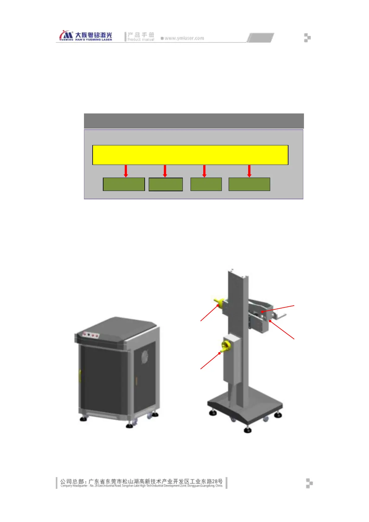
The overall control schematic drawing of the machine is as shown in Fig. 1-5 below:
Fig. 1-5 Overall Machine Control Diagram
1.1.2 Mechanical Components
The mechanical part consists of the console, base, workbench with XY adjustment
platform (optional), assembly line (optional), and rotating platform (optional).
Fig. 1-6 Console Diagram Fig. 1-7 Base Diagram
① Front & rear adjustment