23
Fig. 3-4 Scanning Focus Lens Installation Diagram
3.1.2.4 Connecting Galvanometer Cable
Insert the galvanometer signal cable DB15-pin rectangular connector to the marking
control card CON1 [TO Scanhead] hole rectangular connector in the electric control
board.
Insert the galvanometer power cord with 4-hole circular connector into the
[Galvanometer Power] circular connector socket on the electrical control box, and fix.
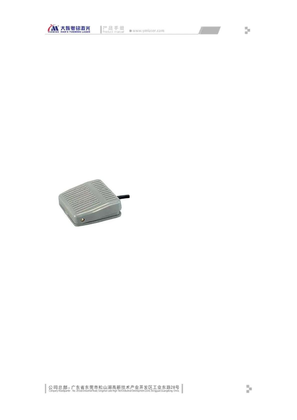
3.1.2.5 Installing Footswitch
Place the foot switch in the lower side of the machine in order for the operator to
trigger the processing with foot, as shown in Fig. 3-5:
Connect the foot switch cable to the aviation plug socket of the [Footswitch input] of
the machine.
Fig. 3-5 Footswitch
3.1.2.6 Installing Sensor and Encoder (marking on the fly optional)
Fix the encoder on the assembly line in accordance with the mechanical installation
requirements, and connect the 6-hole circular connector plug to the circular connector
socket identified as [encoder] on the console, and fix.
Fix the sensor on the assembly line in accordance with the mechanical installation
requirements, connect the 4-hole circular connector plug to the circular connector
socket identified as [sensor] on the console, and fix; then, adjust the sensor testing
height and sensitivity according to the surface of customer workpiece.
3.1.2.7 Equipment Grounding
MF20 laser equipment has strict requirements on safe grounding of user power system,
which must comply with local safety standards: