Page 4
1.2 CONTROL UNITS
1.2.a Microswitches
- A contact resistance of less than 0.1Ω and a current leakage of less than 100µA is
required.
- The key contact must be able to take all the current of the loads without causing a voltage
drop of more than 01.V between contacts.
- Send a voltage signal to the microchip when a function is requested (e.g. start running).
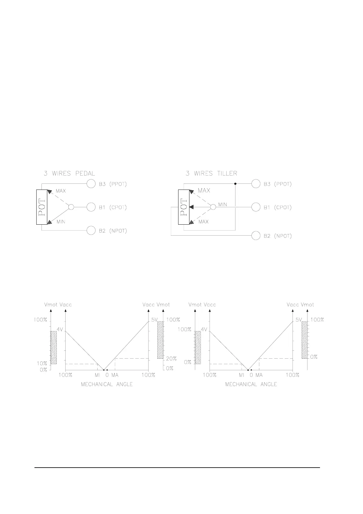
1.2.b Potentiometer
Potentiometer configured with 3 wires.
The CPOT range varies from 0 to 10V.
Minimum resistance: 500 Ω
Maximum resistance: 10KΩ
Automatic minimum and maximum signal acquisition must be carried out (PROGRAM
VACC function) using the programming console and in both directions. This function is
indispensable when compensating an eventual asymmetry in the mechanical components
of the potentiometer and for minimum level adjustment in particular.
The above graphs show the output voltage of a potentiometer that has not been calibrated
compared to the mechanical “zero” of the tiller knob (MI and MA indicate the closing points
of the microswitches, 0 represents the mechanical angle of rotation of the throttle).
The first graph shows the corresponding motor voltage without acquisition; the second
graph shows the corresponding voltage after potentiometer signal acquisition.