Deva 5.8 and Deva 16 Owner’s Manual
Chapter 2
23
Assigning Inputs to Output Channnels
Assigning the audio inputs to output channels is identical to assigning audio inputs to recording channels.
They use the same style matrix and have all the same settings.
Main Menu > Output Mix
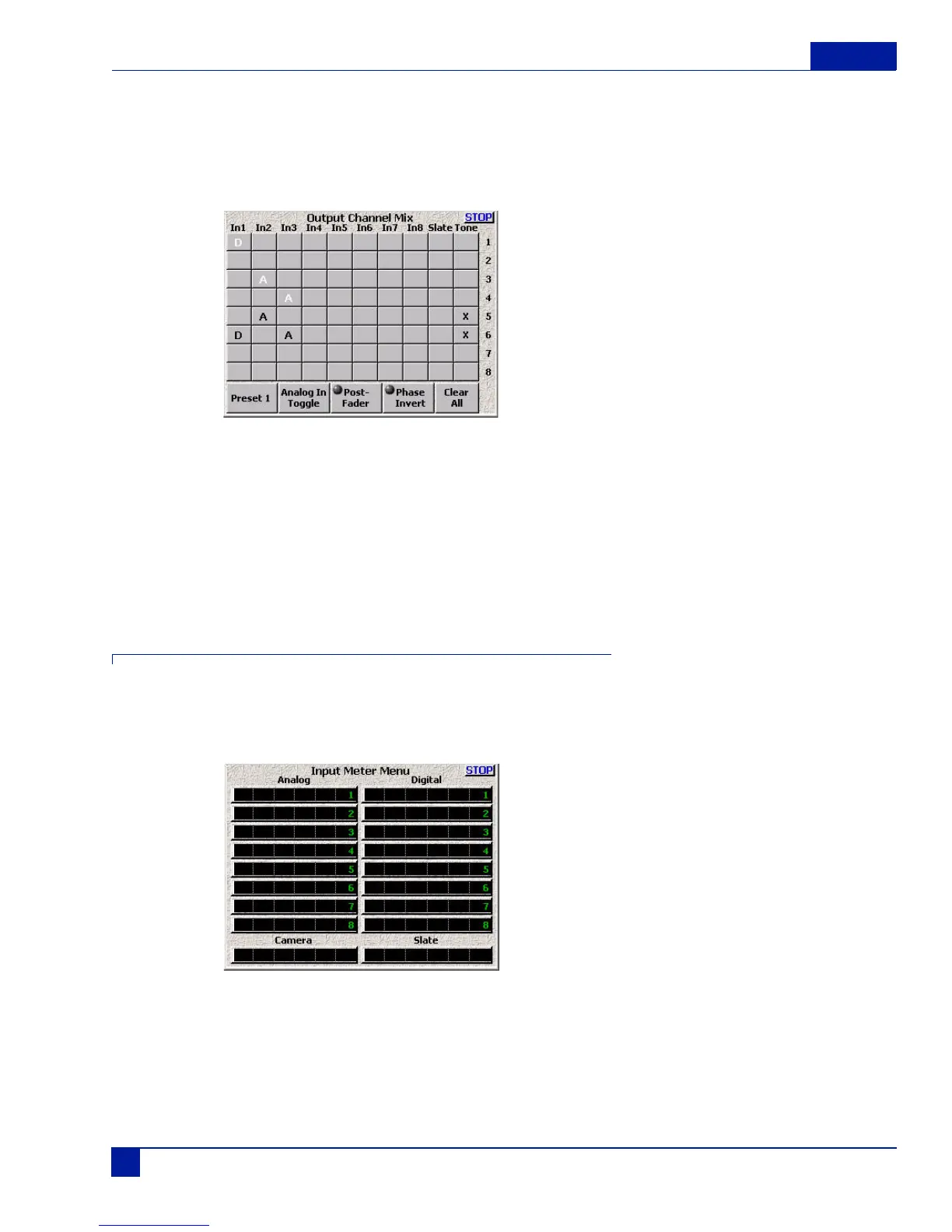
Figure 21 Output Channel Matrix
In Figure 21, Input 1 is a digital signal assigned to two different outputs. Output channel 1 receives a pre-
fader version of the signal, while channel 6 receives a post-fader version of the same signal along with both
a tone signal and post-fader analog signal from input 3. Channel 3 receives a pre-fader version of input 2,
while output 5 receives a post-fader version of input 2 along with a tone signal.
Like the recording matrix, any combination of signals can be assigned to a vast number of output
possibilities.
Overview of Input Signals
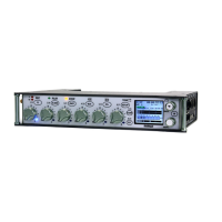
The Input Meter Men provides a quick overview of all input signals. Because of the flexibility of the routing,
you may run into situations where you need to try to determine if a signal is actually coming into the Deva.
Main Menu > Deva Setup > Meters > Display Inputs
Figure 22 Input Meter Menu