Peel/Rewind Upgrade
Install the Rewind Spindle Assembly
10
79835L-001 B ZM400/ZM600 Installation Instruction 7/30/07
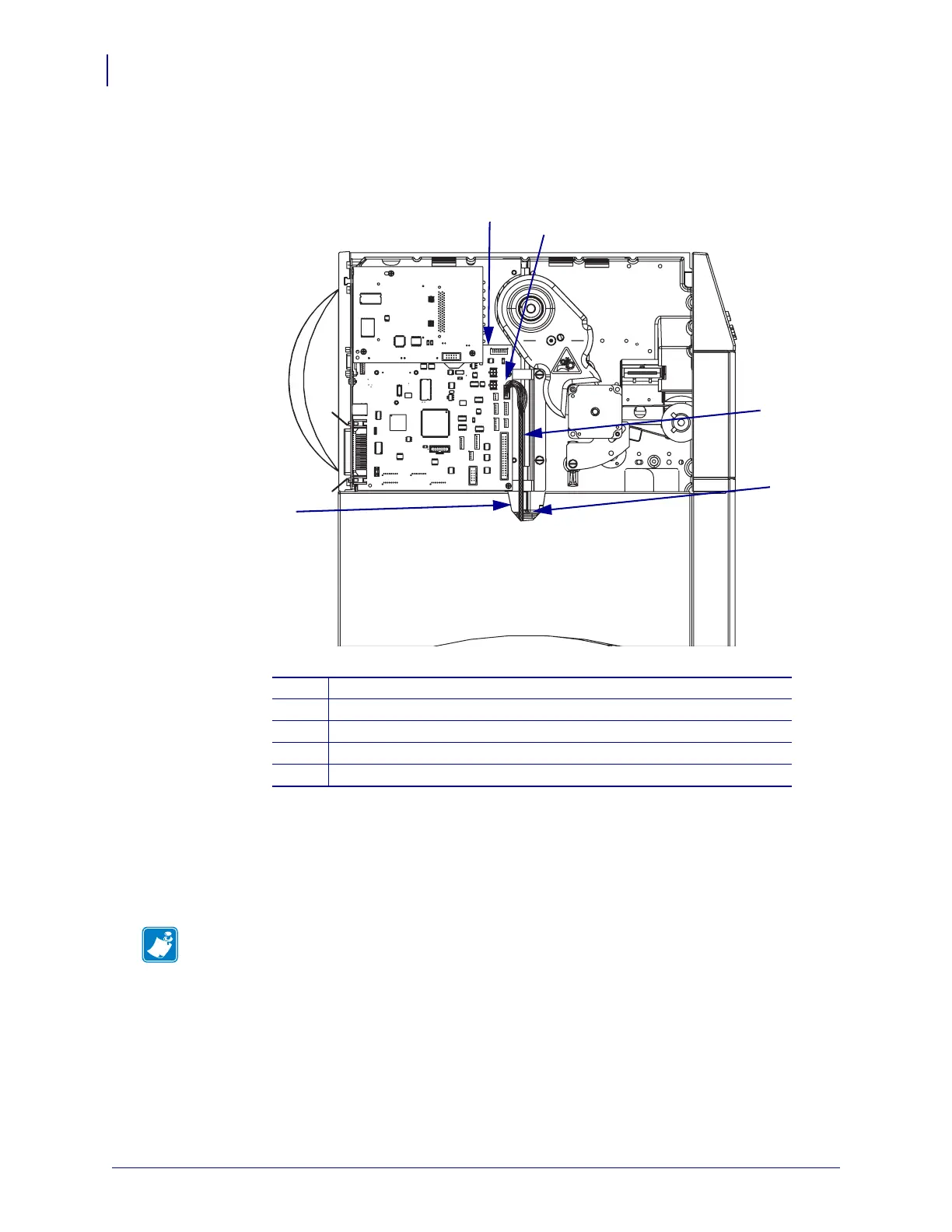
3. See Figure 9. Connect the rewind cable connector to P26 on the main logic board (MLB).
Figure 9 • Connect the Rewind Cable to the Main Logic Board
4. See Figure 10. Align one of the two access holes in the rewind back plate to one of the
mounting holes on the rewind support plate.
5. Using a nut driver, mount the rewind motor and spindle assembly to the printer main
frame using one of the two screws provided.
1
Main logic board
2
Connector P26
3
Rewind cable
4
Access hole
5
Cut away
Note • For ease of alignment, do not tighten the first screw until the second screw is
installed.
5
1
2
3
4
 Loading...

