DALIBOX Interface 64/32
http://www.zennio.com Technical Support: http://support.zennio.com
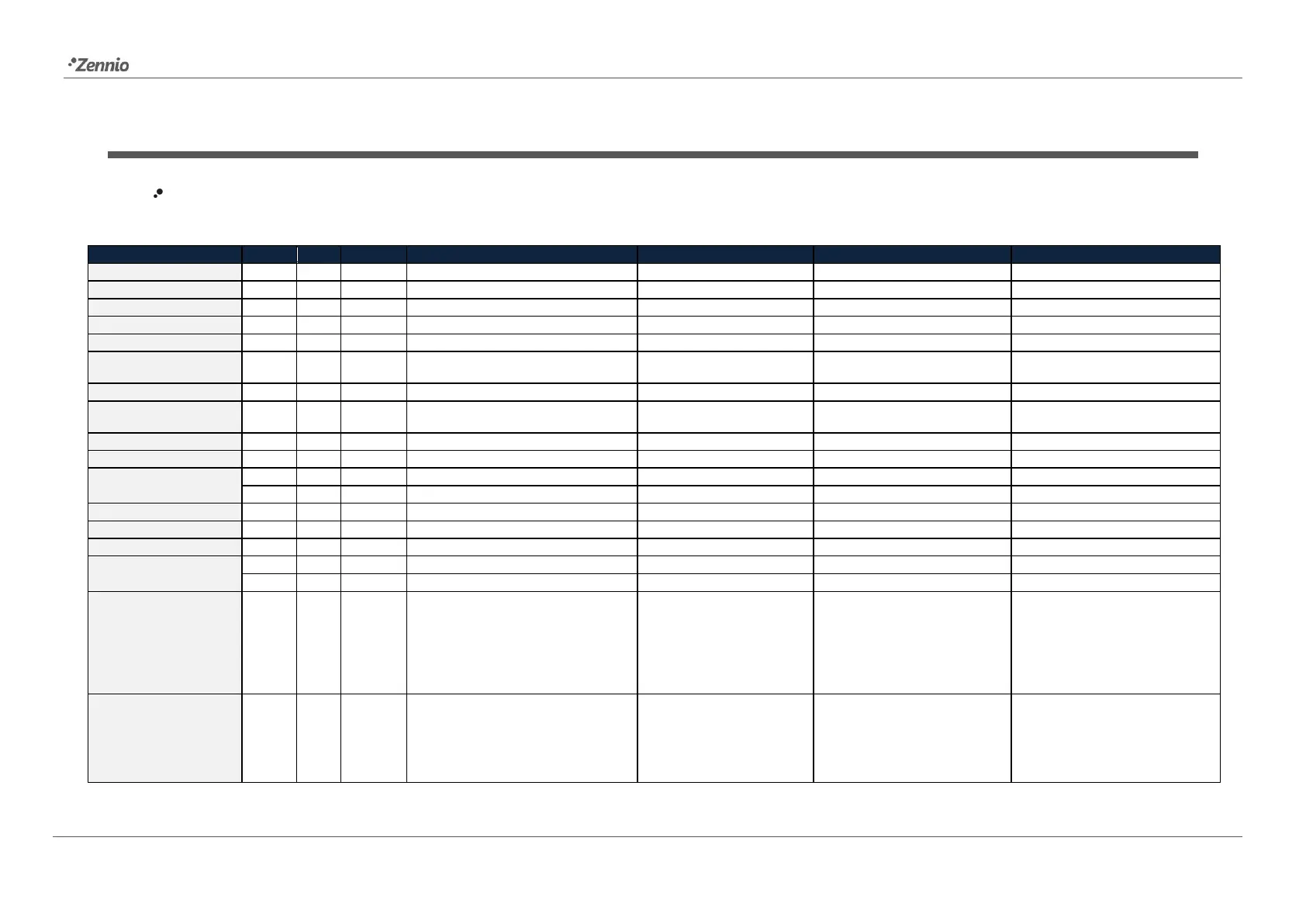
ANNEX I. COMMUNICATION OBJECTS
“Functional range” shows the values that, with independence of any other values permitted by the bus according to the object size, may be of any use or have a particular meaning because of the
specifications or restrictions from both the KNX standard or the application programme itself.
Scene Number + Activate/Learn
Sequence Number + Start/Stop
0 = No Error; 1 = DALI Power
Supply Failure
0 = No Error; 1 = Short Circuit
0 = No Error; 1 = ECG Presence
Failure
DPT_DALI_Control_Gear_Diagnostics
0 = Standby Off; 1 = Standby On
0 = Standby On; 1 = Standby Off
[Heartbeat] Object to Send '1'
Sending of '1' Periodically
18, 29, 40, 51, 62, 73,
84, 95, 106, 117, 128,
139, 150, 161, 172, 183,
194, 205, 216, 227, 238,
249, 260, 271, 282, 293,
304, 315, 326, 337, 348,
359
19, 30, 41, 52, 63, 74,
85, 96, 107, 118, 129,
140, 151, 162, 173, 184,
195, 206, 217, 228, 239,
250, 261, 272, 283, 294,
0x0 (Stop)
0x1 (Dec. by 100%)
...
0x7 (Dec. by 1%)
0x8 (Stop)
0xD (Inc. by 100%)
[Group x] Relative Dimming
 Loading...