1.2 INSTALLATION
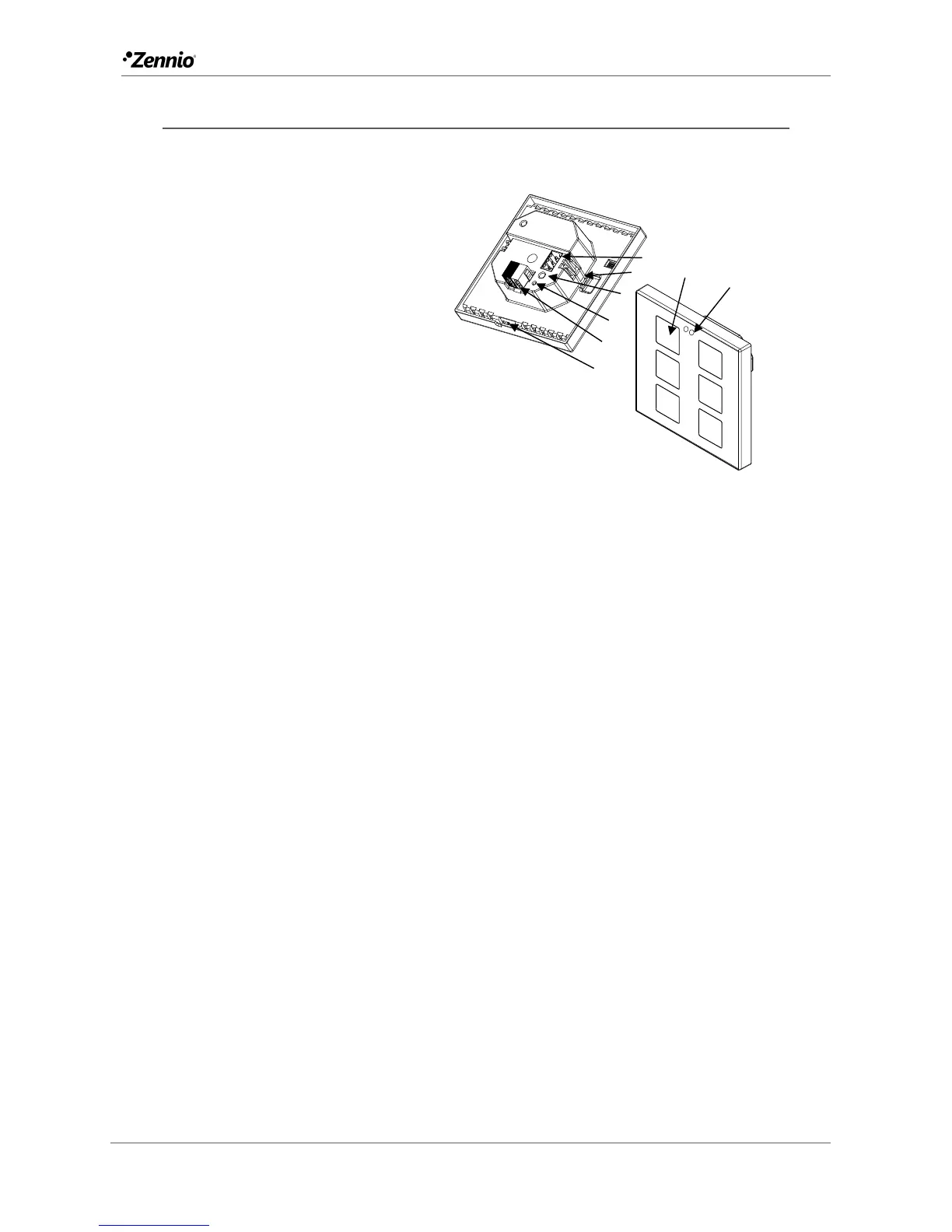
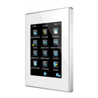
Figure 1 shows the connection outline of the device:
Figure 1 Schematic diagram.
Flat / Flat 55 are connected to the KNX bus through the built-in terminal (2). An
external DC power supply is not needed.
A short press on the Prog. /Test button (4) will make the device enter the
programming mode. The Prog. /Test LED (3) will then light in red. On the contrary, if
this button is held while the device gets connected to the bus, the device will enter the
safe mode. In such case, the programming LED will blink in red colour.
For detailed information about the technical features of Flat / Flat 55, as well as on
security and installation procedures, please refer to the device Datasheet, bundled
within the device packaging and also available at www.zennio.com.
1. Temperature Probe (only in Flat).
2. KNX Connector.
3. Programming LED.
4. Programming Button.
5. Attachment Clip.
6. Input Connectors (In Flat 55, the
position may vary slightly).
7. Touch Buttons.
8. Proximity and Luminosity Sensors.