Motherboard Installation
Page 8
ATX Power Connector
A single 20-pin connector incorporates standard ±5V and ±12V, optional 3.3V and soft-power signals.
With a power supply supports remote power on/off, the motherboard can turn off the system power
through software control, such as the shutdown in Windows 95 Start menu. The system BIOS will turn
the system power off when it receives the proper APM command from the OS. APM must be enabled in
the system BIOS and OS in order for the soft-off feature to work correctly.
Pin Signal Name Pin Signal Name
1 +3.3V 11 +3.3V
2 +3.3V 12 -12V
3 Ground 13 Ground
4 +5V 14 PW_ON
5 Ground 15 Ground
6 +5V 16 Ground
7 Ground 17 Ground
8 PWRGOOD 18 -5V
9 +5VSB 19 +5V
10 +12V 20 +5V
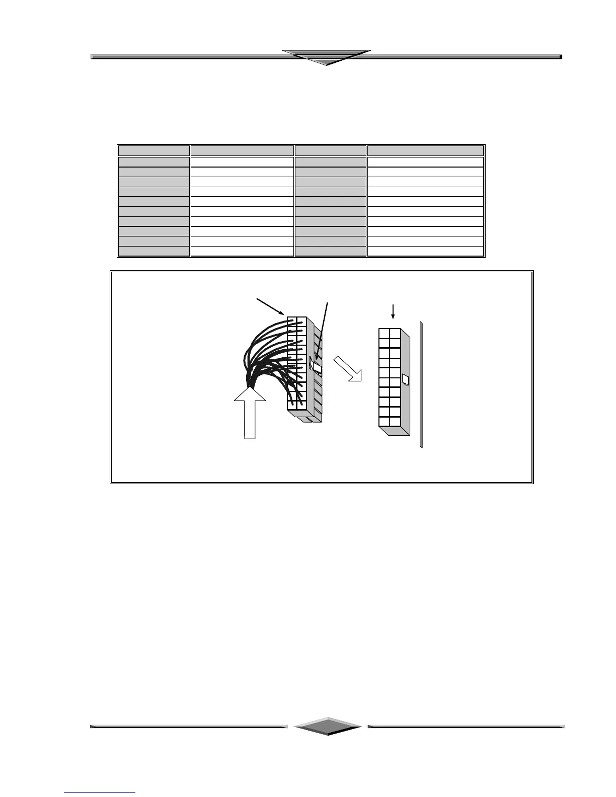
From ATX Regulated
Power Supply
6DXP Motherboard
ATX Power Connector
Connector's Lock
(push to release)
PW1
Onboard receptacle
ATX Power Connector Installation
Floppy Drive Connector
This 34-pin connector supports the provided floppy drive ribbon cable. After connecting the single end to
the on-board “FLOPPY” connector, connect the remaining plugs on the other end to the floppy drives
correspondingly.
IDE Connectors
The two on-board IDE connectors support the provided 40-pin IDE hard disk ribbon cable. After
connecting the single end to the board, connect the two remaining plugs at the other end of your hard
disk(s). If you install two hard disks, you must configure the two drives by setting its jumpers according to
the documentation of your hard disk. Also, you may connect the two hard disks to be both Masters using
one ribbon cable on the primary IDE connector and one on the secondary IDE connector.