Motherboard Installation
Page 9
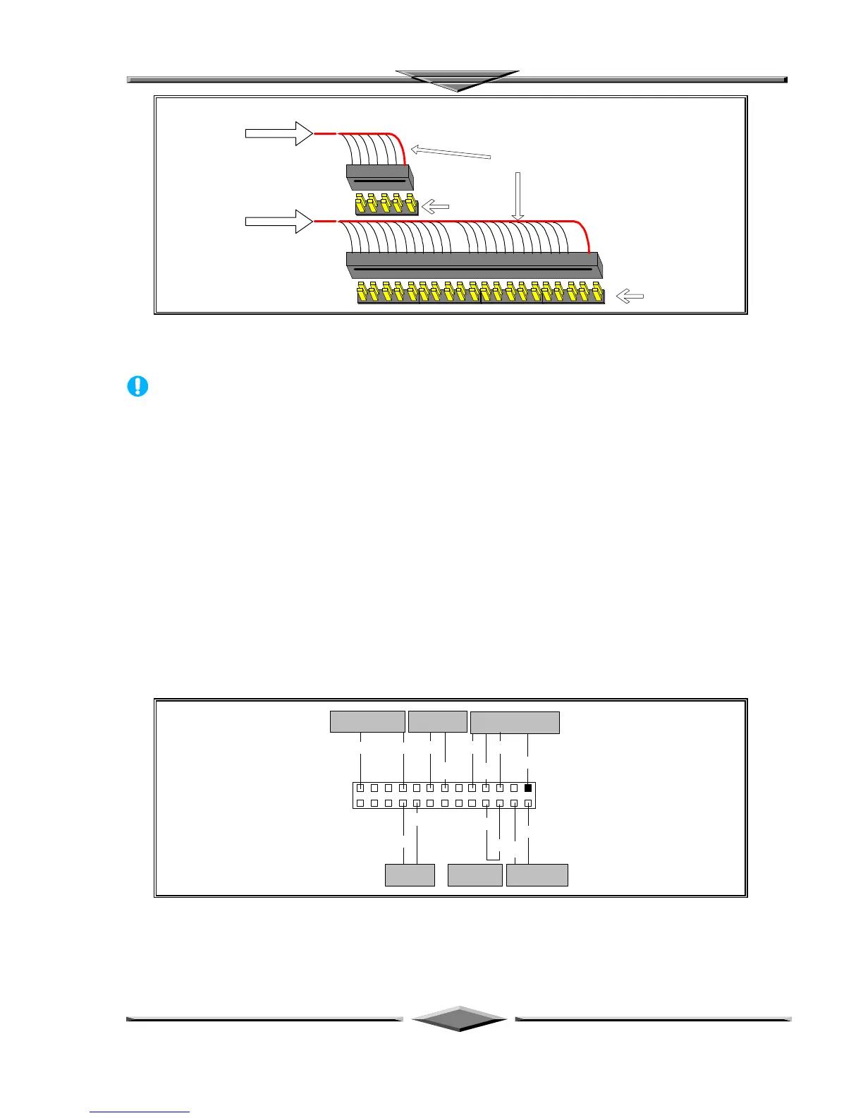
Red Wire Side
Pin 1 Side
Pin 1 Side
Provided 10 Pin
Ribbon cable
Provided 40 Pin
Ribbon cable
Ribbon cable Installation Example
NOTICE
For the flat ribbon cable connection, please make sure that the pin 1 of the ribbon cable
(the red wire side of the cable) is correctly connected to the on-board connector’s pin 1 as
shown on the “Map of the Motherboard”.
Front Panel Function Connectors
All the front panel indicator, speaker, and switch functions are grouped into a on-board 26-pin connector,
J5. Front panel features supported include:
• System Reset, RESET
• Power LED, form KEYLOCK
• Hard Drive activity LED, IDE LED
• System Speaker, SPEAKER
• Soft-touch button power on/off, SW ON
• External power saving control, EXTSMI (optional)
The connector pin out are described as the figure below:
KEY
LOCK
KEYLOCK
SPEAKER EXTSMI
PWBTRESET IDE LED
J5
13
26 14
GND
VCC
SPKR
PW LED
GND GND
EXT
SMI
RST
GND
IDE
LED
GND
PUSH-ON
SBV
The Onboard Function Connector Pin Out