Motherboard Installation
Page 7
EXPANSION CARDS INSTALLATION
At the most of beginning, you must read your expansion card documentation on any hardware and
software settings that may be required. The installation procedures are summarized as below:
1. Read the User’s Guide/Manual of your expansion card.
2. If necessary, set any jumpers on your expansion card.
3. Power-off the system and then disconnected the power cord.
4. Remove your computer’s cover.
5. Remove the metal bracket from one of the empty slot, ISA or PCI, corresponding to the type
of expansion card.
6. Carefully align the card’s connectors and press firmly, make sure that the connection is
good.
7. Secure the card on the slot.
8. Replace the computer’s cover.
9. Setup the BIOS configuration if necessary.
10. Install the required software drivers for your expansion card.
CAUTION
Before adding or removing any expansion card or other system components, make sure
that you unplug your system power supply. Failure to do so may cause damage of your
motherboard and expansion cards.
CONNECTING EXTERNAL CONNECTOR
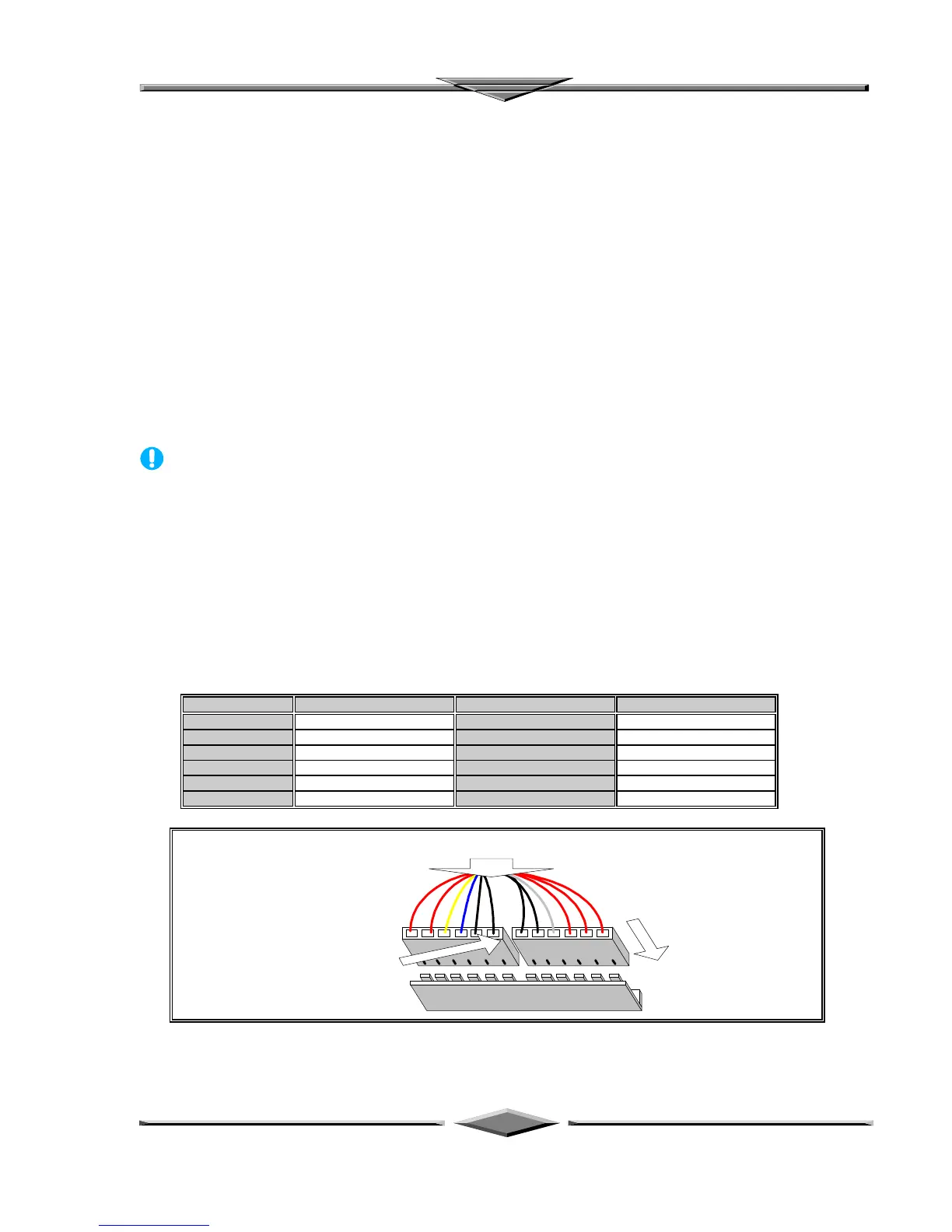
AT Power Connector
A 12-Pin power supplies provide two plugs incorporates standard ±5V and ±12V, each containing six
wires, two of which are black. Orient the connectors so that the black wires are together.
Pin Signal Name Pin Signal Name
1 Power Good Signal 7 Ground
2 +5V 8 Ground
3 +12V 9 -5V
4 -12V 10 +5V
5 Ground 11 +5V
6 Ground 12 +5V
Two 6-Pin Plugs
From AT Power Supply
Vertically Insert
For Installation
Place 2 Black Wires,
On Each Of The
Plug, Closed To The
Centre
AT Power Connector Installation