4. Simple turnout control (the first time)
Operating turnouts and signals in the MX32 follows an object-oriented approach: In a "panel" of turn-
out and signal icons (the "panel" as a precursor to the track diagram), the individual "object" is operated
by pressing the corresponding function key. Each object or display icon must be assigned to the corre-
sponding decoder address (and/or sub address, number etc.) in a previously executed definition
process.
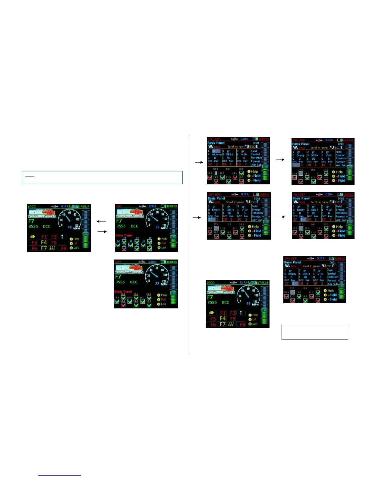
W- Key (from LOCO mode) Operating mode SWI: the lower display half shows a “Basis Panel”
filled with 18 “V” symbols, of which 9 are visible:
Numeric keys 1…9 operate the visible icons.
The 18 fields of the “Sample Panel” are preas-
signed to the accessory decoder addresses 10.0,
10.1, 10.2, 10.3, 11.0, 11.1, 11.2… with its 4 sub
addresses (0…3).
(Shift) displays the decoder addresses instead
of the field numbers. .
Scrolling wheel Scrolls within the panel
The default “V symbols” can be interpreted as uni-
versal left-right switches or as red-green signals.
They are, however, not real switchboard fields but
can be exchanged with proper icons (on the SWI
DEF definitions page).
The quickest way to change the default accessory addresses is with this shortcut:
(Shift) + W + (Shift) Opens the SWI DEF page, but (because of ) the cursor jumps immediately
to the address input line (with sub addresses…) and enables the “inline scroll option”, which al-
lows the addresses to be changed one by one without any further scrolling, confirming each with
the A-Key; use the U-Key to switch between “scroll in line” / “scroll panels”.
(SHIFT) + W (without the extra (Shift)) Opens the definition’s page. Start with the top left field
gr/rg – setting, go to all other fields using the scrolling wheel.
Exit to the SWI panel after the desired changes are made in SWI DEF with:
W- Key saves the newly entered data
(i.e. the addresses) and returns
to the SWI mode.
E- Key exits the definition screen WITHOUT
saving, back to SWI
W- Key returns to the LOCO mode.
 Loading...