ES-3124 Series User’s Guide
List of Figures 23
List of Figures
Figure 1 Backbone Application ............................................................................. 39
Figure 2 Bridging Application ............................................................................... 39
Figure 3 High Performance Switched Application ................................................. 40
Figure 4 Tag-based VLAN Application .................................................................. 41
Figure 5 Shared Server Using VLAN Example ..................................................... 41
Figure 6 Attaching Rubber Feet ........................................................................... 43
Figure 7 Attaching the Mounting Brackets ............................................................ 44
Figure 8 Mounting the Switch on a Rack ............................................................. 45
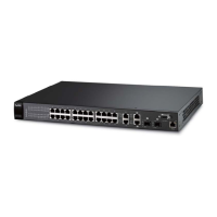
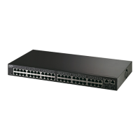
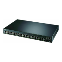
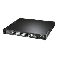
Figure 9 Front Panel: ES-3124 ............................................................................ 47
Figure 10 Front Panel: ES-3124-4F ..................................................................... 47
Figure 11 Front Panel: ES-3124PWR .................................................................. 48
Figure 12 Front Panel: ES-3124F ........................................................................ 48
Figure 13 Transceiver Installation Example .......................................................... 51
Figure 14 Installed Transceiver ............................................................................ 51
Figure 15 Opening the Transceiver’s Latch Example ........................................... 51
Figure 16 Transceiver Removal Example ............................................................. 51
Figure 17 Rear Panel (AC models) ....................................................................... 52
Figure 18 Rear Panel (DC models) ....................................................................... 52
Figure 19 Web Configurator: Login ....................................................................... 56
Figure 20 Web Configurator Home Screen (Status) .............................................. 56
Figure 21 Change Administrator Login Password ................................................. 61
Figure 22 Example Xmodem Upload ..................................................................... 63
Figure 23 Reload the Configuration file: Via Console Port ................................... 63
Figure 24 Resetting the Switch: Via the Console Port .......................................... 64
Figure 25 Web Configurator: Logout Screen ........................................................ 64
Figure 26 Initial Setup Network Example: VLAN ................................................... 65
Figure 27 Initial Setup Network Example: Port VID .............................................. 67
Figure 28 Initial Setup Example: Management IP Address ................................... 67
Figure 29 Status (ES-3124PWR) .......................................................................... 70
Figure 30 Status (ES-3124-4F) ............................................................................. 70
Figure 31 Status: Port Details (ES-3124PWR) ...................................................... 72
Figure 32 Status: Port Details (ES-3124-4F) ......................................................... 73
Figure 33 System Info (ES-3124PWR) ................................................................. 78
Figure 34 System Info (ES-3124-4F) .................................................................... 79
Figure 35 General Setup ....................................................................................... 81
Figure 36 Switch Setup ......................................................................................... 83
Figure 37 IP Setup ................................................................................................ 86
Figure 38 Port Setup (ES-3124PWR) ................................................................... 89
 Loading...