EasyManuals Logo

2N Helios IP Installation Manual

2N Helios IP
44 pages
To Next Page IconTo Next Page
To Previous Page IconTo Previous Page
Page #27 background imageLoading...
Page #27 background image
Electric Installation
2.3
23
2.3 Electric Installation
This subsection describes how to connect 2N
®
Helios IP Safety into your Local Area
Network (LAN) and how to connect supply voltage and the electric lock.
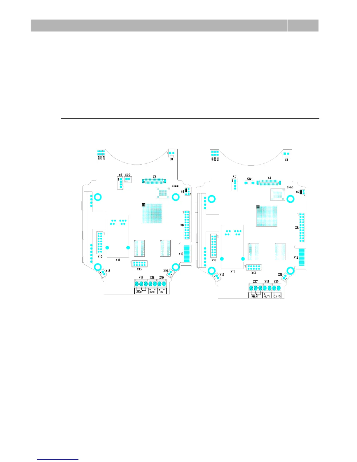
PCB Connectors
Fig. 2.11 shows the lay-out of connectors on the 2N
®
Helios IP Safety printed circuit
board (PCB). Cables, accessories and other system components are connected to
connectors X1 through X22.
Figure 2.11 2N
®
Helios IP Safety Connectors, PCB Version 555v2 and 555v3

Other manuals for 2N Helios IP

Questions and Answers:

Question and Answer IconNeed help?

Do you have a question about the 2N Helios IP and is the answer not in the manual?

2N Helios IP Specifications

General IconGeneral
TypeIP Intercom
ConnectivityEthernet
Tamper SwitchYes
AudioFull duplex
MicrophoneBuilt-in
SpeakerBuilt-in
CameraYes
Power SupplyPoE
Operating Temperature+60°C
Ingress ProtectionIP54
ProtocolsSIP, RTSP, ONVIF
Audio CodecG.711, G.722
InstallationSurface mount, flush mount (depending on model)

Related product manuals