3
Food Services Trade Department
3M Center, Building 551-1E-02
St. Paul, MN 55144-1000
Printed on 50% recycled
waste paper, including 10%
post-consumer waste paper.
Printed in U.S.A.
3M 2000 May
78-6912-0712-6 Rev. B
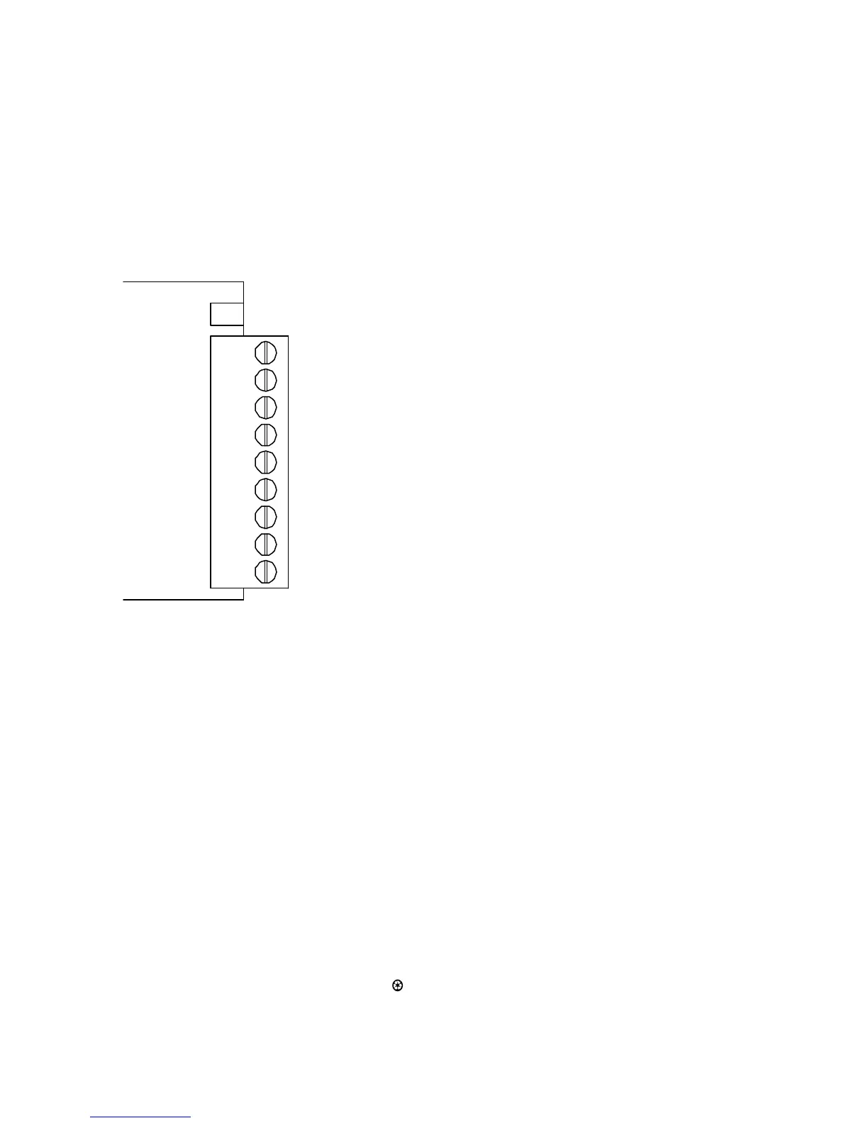
Wiring Diagram
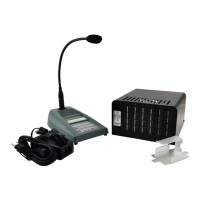
Wiring the A200
Connect the loop wires to terminals 1 and 2 and the shield to 3. Terminals 4 through 9 are available to
trigger external devices. Connect the included 12VDC power supply from the 12VDC jack to a 120 VAC
electrical outlet.
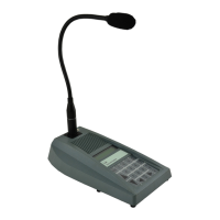
Wiring the A201
Connect the loop wires to terminals 1 and 2 and the shield to 3. 12 VDC power and terminals 7, 8, and 9 are
connected to the C921BA Base Station through the ribbon cable. Terminals 4, 5, and 6 are available to
trigger external devices.
8 - COM
7 - N. O.
6 - N. C.
5 - COM
4 - N. O.
3 - EARTH
2 - LOOP
9 - N. C.
1 - LOOP
12 VDC
Figure 5. A200/A201 Terminals