4. Turn on both base stations and press the RESET SWITCH on each of the base station circuit boards to “read”
the jumper setting into the microprocessor.
5. Select a channel for each of the base stations. (See page 14 for the channel selection procedure.) After you
select the channel, press the RESET SWITCH on the base station circuit boards to “read” the selection into
the microprocessor.
6. Re–program the headsets as instructed on page 15.
7.
Check the operation of each of the systems. Note that the alert tone for the Lane 1 system headsets is a
single repeating “beep” while the alert tone for the Lane 2 system headsets is a double repeating “beep.”
Cross-Lane System Installation
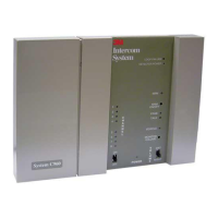
The Cross-Lane system provides communication for facilities that have two menu signs. It consists of two base
stations that are connected to a Cross-Lane Module. A Cross-Lane Module is a five-pole switch that allows the
two systems to be separated during hours of peak activity. Refer to the installation instructions included with the
Cross Lane Module (78–6911–4396–6). These instructions are also located in the C960 Service Manual.
A Cross-Lane Module can be useful if the manager wishes to operate each lane with a separate crew during
periods of peak activity. This is accomplished by turning the Cross-Lane switch OFF. By pressing the T1 button
on any headset, the operator can communicate with a customer at menu sign 1. By pressing the T2 button on any
headset, another operator can communicate with a customer at menu sign 2. When the Cross-Lane Module is
OFF, the operator will only hear the vehicle detector alert from the menu sign with which he or she last talked.
During periods of lower activity, the Cross-Lane Module is turned ON, allowing one headset order-taker to
operate both lanes. When the cross-lane module is turned ON, the operator will always hear vehicle detector
alerts from both menu signs. A single alert indicates a vehicle is at menu sign 1 while a double alert indicates a
vehicle is at menu sign 2.