ModelC960Headset IntercomSystemOperation and Diagrams
1-6 E 3M 2000 May
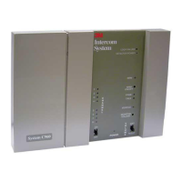
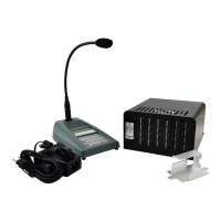
Base Station
n Note
Receiver/transmitter and logic circuitrycontained
in the C960 headset intercom base station is both
proprietary and non-field repairable. For this
reason, the accompanying base station diagram
provides no circuitcomponent detail. Onlythose
details that assist fault isolation (such as
connections,configurationjumpers,audiocontrol
circuits,replaceablecomponents andinput/output
functions) are shown.
DC Power
DC power for the base station circuits and external
components is provided as follows:
Aself-containedDCpowertransformer,connectedto
120VAC, providesunregulated +12VDCto thebase
station power input jack. The +12VDCis turned on
oroffbyaslideswitchlocated onthefrontofthebase
station. The unregulated +DC is routed through a
protective polyswitch (circuit breaker) to circuit
components and a voltage regulator (called power
supply in the diagram). If an overcurrent condition
causesthepolyswitch toopen,itautomaticallyresets
after power is removed.
The unregulated +12VDC is used by the vehicle
detectortoprovide a+DCvehicledetect signaltothe
basestationvehicledetectcircuits. If aninterconnect
module is used in the system, unregulated +DC is
providedtoenergize theinterconnectmodulerelays.
Talk/Page Input
Talkandpagevoicecommunicationstransmittedfrom
the headset are received along with their
accompanying “talk” or “page” control tones.
Received talk communications are routed by the
RCVR & RCVR LOGIC as follows:
S To the menu sign speaker amplifier via the
DAY/NIGHTvolumecontrols andDAY/NIGHT
switch, through the amplifier to the menu sign
S To the monitor speaker amplifier via the MON
TALKvolumecontrol, throughtheamplifierand
theMasterMonitorVolumecontroltothemonitor
speaker
S Through the transmit amplifier to the TXMT &
TXMT LOGIC for transmission to all headset
receiversandto outputconnectorpin9 forusein
cross-lane applications
Received page communications are routed by the
RCVR & RCVR LOGIC as follows:
S To the monitor speaker amplifier via the MON
PAGEvolumecontrol, throughtheamplifierand
theMasterMonitorVolumecontroltothemonitor
speaker
S Through the transmit amplifier to the TXMT &
TXMT LOGIC for transmission to all headset
receivers,andtooutputconnectorpin 9forusein
cross-lane applications
Vehicle Detector Input
Upon detection of a vehicle, the vehicle detector
signal will be a steady DC or a short-duration DC
pulsedependingon whetherthe vehicledetector is a
“presence”or“pulse” typedetector. Upon receiptof
the vehicle detect signal, the VEHICLE DETECT
LOGICcircuitemits alerttones. Thesealerttonesare
routed as follows:
S To the monitor speaker amplifier via the MON
ALERT volume control, through the monitor
speakeramplifierandtheMasterMonitorvolume
control to the monitor speaker
S To the transmit amplifier via the Headset Alert
Levelcontrol,throughthe amplifiertotheTXMT
& TXMT LOGIC for transmission to all headset
receivers
S To output connector pin 12 foruse incross-lane
applications