Illustrations
Figure 1. Typical Installation............................................................................................................... 1
Figure 2. Battery Chargers (3–Slot and 6–Slot Versions)....................................................................... 2
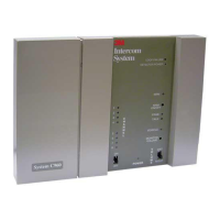
Figure 3. Base Station Mounting Holes................................................................................................ 3
Figure 4. Interconnect Module............................................................................................................. 4
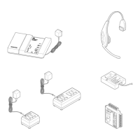
Figure 5. Direct Base Station–to–Component Connections.................................................................... 5
Figure 6. Base Station – Interconnect Module Connections.................................................................... 6
Figure 7. Connecting Components to the Interconnect Module .............................................................. 7
Figure 8. D–15D (M478 DA) Connections........................................................................................... 8
Figure 9. D–15B and D–15C (M478 BA and CA) Connections.............................................................. 8
Figure 10. D–30 Connections .............................................................................................................. 9
Figure 11. Cross–Lane Wiring Diagram............................................................................................... 11
Figure 12. Removing the Half–Cover from the Base Station.................................................................. 16
Figure 13. Base Station Circuit Board .................................................................................................. 17
Figure 14. Base Station Circuit Board .................................................................................................. 21