23
7-3-5-2 Calibration of Feedback signal
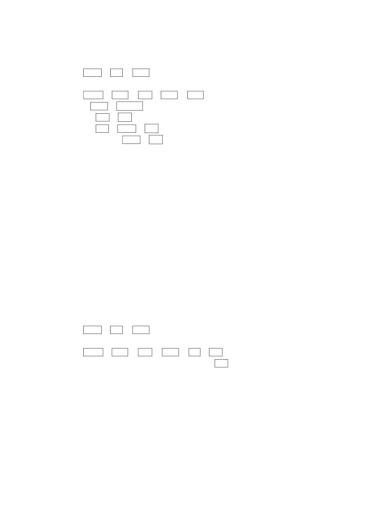
Below is operating sequence IOUT (Feedback signal)
○ Sequence
①Unlock
LOCK ⏎ LK? ▼ ULK? ⏎
②Operation
MANU ⏎ SPLT ▼ SUB ⏎ DIAG ▼ IOUT
⏎ VIEW ⏎ **.** mA : Display feedback signal value
▼ ACT ⏎ **** ⏎ : Set the direction of feedback signal. (4 to 20 or 20 to 4)
▼ ADJ ⏎ ZERO ⏎ **** ⏎ : Set the current output of feedback signal at 0%
▼ SPAN ⏎ **** ⏎ : Set the current output of feedback signal at 100%
○ Notice
・It can have this set in the specification does not have feedback signal. But feedback signal
can not be used.
・Default direction of feedback signal is 4 to 20 mA.
・The current output count of feedback signal is 0 by default, for both 4 mA and 20 mA. The
current output changes 0.00989 mA by 1 count.
7-3-5-3 Torque motor
Adjust torque motor. It is set the value adapted to the conditions of use in the A-2 tuning. It is not
recommended to change.
7-3-5-4 Direction D / R
Choose Direct /Revers acting mode. It is set the value adapted to the conditions of use in the A-1
tuning. It is not recommended to change.
○ Sequence
①Unlock
LOCK ⏎ LK? ▼ ULK? ⏎
②Operation
MANU ⏎ SPLT ▼ SUB ▼ DIAG ▼ D/R ⏎ DA? ⏎ : Direct acting mode
▼ RA? ⏎ : Reverse acting mode
○ Notice
・DA means that the valve position is reduced when the input signal is increased.
・RA means that the valve position is increased when the input signal is increased.