4
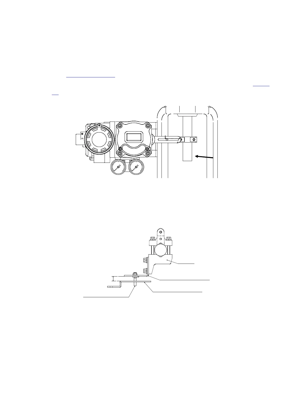
2) Install positioner and lever
① Install positioner
When the sensor angle is 0° (Valve Stem and Feedback lever is vertical), the positioner Feedback
lever is mounted the positioner so that the horizontal. When this location is shifted, it is cause of
linearity errors.
※Sensor angle has become the center allocation. Confirmation of the sensor angle, please refer
to the 7-3-4-9 Display angle.
※Misalignment of mounting position can be corrected by setting. Please refer to P50P in 7-3-4-2
FB.
② Keep levers parallel
Insert Transmission pin into long hole of Feedback lever A to install positioner
The Feedback lever A and B should be parallel to each other. If not mounted in parallel, it is cause
of linearity errors.
Clamp
Feedback Lever B
Feedback Lever A
Transmission Pin
Parallel