14
THERMAL EXPANSION
As water is heated, it expands (thermal expansion). In a closed
system the volume of water will grow when it is heated. As the
volume of water grows there will be a corresponding increase in
water pressure due to thermal expansion. Thermal expansion can
cause premature tank failure (leakage). This type of failure is not
covered under the limited warranty. Thermal expansion can also
cause intermittent temperature-pressure relief valve operation:
water discharged from the valve due to excessive pressure build
up. This condition is not covered under the limited warranty. The
temperature-pressure relief valve is not intended for the constant
relief of thermal expansion.
A properly sized thermal expansion tank should be installed on all
closed systems to control the harmful eects of thermal expansion.
Contact a local plumbing service agency to have a thermal expansion
tank installed.
ELECTRICAL
The installation must conform with these instructions and the local/
national code authority having jurisdiction and the requirements
of the power company. In the absence of local/national codes, the
installation must comply with the current editions of the
National
Electrical Code
,
NFPA 70
or the
Canadian Electrical Code CSA C22.1
.
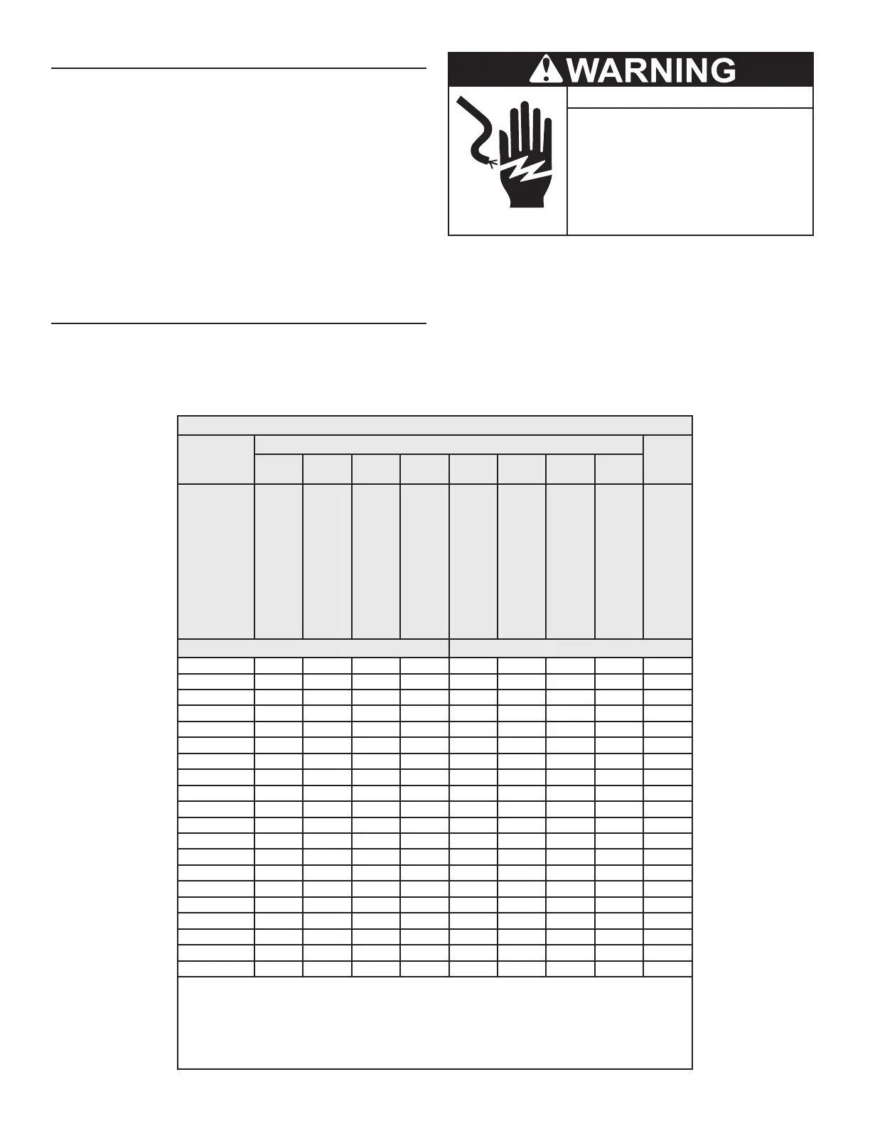
● Before removing any access panels or
servicing the water heater, make sure
the the electrical supply to the water
heater is turned OFF.
Electrical Shock Hazard
● Failure to follow these instructions can
result in personal injury or death.
An electrical ground is required to reduce risk of electrical shock
or possible electrocution. The water heater shall be connected to a
separate grounded branch circuit with over-current protection and an
all pole, full disconnect switch. The water heater shall be grounded
in accordance with Local/National codes.
Voltage applied to the heater should not vary more than +5% to -10%
of the model and rating plate marking for satisfactory operation. See
Model And Rating
(page 10).
All eld wiring to be installed in approved conduit per local Local/
National codes.
Table 4. Allowable Ampacities of Insulated Conductors
1
Size
Temperature Rating of Conductor
Size
140 °F
(60 °C)
167 °F
( 75 °C)
185 °F
(85 °C)
(194 °F)
(90 °C)
140 °F
(60 °C)
167 °F
( 75 °C)
185 °F
(85 °C)
194 °F
(90 °C)
AWG MCM
Types
RUW,
TTW,
and UF
Types
FEPW,
H,
RHW,
RUH,
HW,
THWN,
XHHW,
USE,
and
ZW
Types
V, and
MI
Types
TA,
TBS,
SA,
AVB,
SIS,
EP
2
,
FEPB
2
,
RHH
2
,
THHN
2
,
and
XHHW
2,
3
Types
RUW,
TTW,
and UF
Types
RH,
RHW,
RUH,
THW,
THWN,
XHHW,
and
USE
Types
V, and
MI
Types
TA,
TBS,
SA,
AVB,
SIS,
RHH
2
,
THHN
2
,
and
XHHW
2,
3
AWG
MCM
Copper Aluminum or Copper-Clad Aluminum
18 .... .... .... 21 .... .... .... .... ....
16 .... .... 22 22 .... .... .... .... ....
14 15 15 25 25 .... .... .... .... ....
12 20 20 30 30 15 15 25 25 12
10 30 30 40 40 25 25 30 30 10
8 40 45 50 50 30 40 40 40 8
6 55 65 70 70 40 50 55 55 6
4 70 85 90 90 55 65 70 70 4
3 80 100 105 105 65 75 80 80 3
2 115 120 120 75 90 95 95 2
1 130 140 140 100 110 110 1
0 150 155 155 120 125 125 0
00 175 185 185 135 145 145 00
000 200 210 210 155 165 165 000
0000 230 235 285 180 185 185 0000
250 255 270 270 205 215 215 250
300 285 300 300 230 240 240 300
350 310 325 325 250 260 260 350
400 335 360 360 270 290 290 400
500 380 405 405 310 330 330 500
1. Not more than three conductors in raceway, cable, or earth (directly buried), based on ambient temperature of
86°F (30°C).
2. +The load current rating and the over-current protection for these conductors shall not exceed 15 amperes
for 14 AWG. 20 amperes for 12 AWG and 30 amperes for 10 AWG copper; or 15 amperes for 12 AWG and 25
amperes for 10 AWG aluminum and copper-clad aluminum.
3. *For dry locations only. See 167 °F (75°C) column for wet locations.
Table taken from the
National Electric Code, NFPA 70
(United States))
Printed on 5/6/2022 7:17 AM CT
 Loading...