11
Electrical
Connection terminations are made to the
main terminal block of the controller and the
HVAC equipment.
A complete set of unit specific wiring
diagrams, showing factory and field wiring
are laminated in plastic and located inside
the controls compartment door of the AAON
HVAC equipment.
Control Wiring
Control wiring size must be large enough to
prevent excess voltage drop and ensure
proper operation. Control voltage returning
from controller circuit must be a minimum
of 21 VAC. To assure proper wiring use the
following table to determine the allowable
wiring distances.
Table 1 - Control Wiring
Wire Size (Stranded)
- Copper Conductors
Only
Total Wire Distance
Allowable
Total Wire Distance Allowable =
(Quantity of Control Wires) x
(Control Wire Distance)
Take the total wire distance allowable and
divide by the quantity of wires to be
connected. This indicates the distance
allowable for that size wire. The wiring to
the unit must not exceed the total wire
distance allowable. If the voltage at the
connectors is less than 21 VAC, isolation
relays must be installed. If under external
control 21 VAC must be field verified.
All external devices must be powered via a
separate external power supply.
Example:
A total of 8 wires must be pulled 75 ft to a
control the unit. What size wire should be
used?
According to Table 1, 16 AWG allows for
63 ft (500 ft/8 wires) and 14 AWG allows
for 94 ft (750 ft/8 wires). Thus, 14 AWG
should be used.
BACnet MS/TP EIA-485 Wiring
Connect the -A terminals in parallel with all
other -A terminals on the network and the
+B terminals in parallel with all other +B
terminals. Connect the shields of the cable
together at each device using a wire nut.
Connect the cable shield to a good earth
ground at one end only.
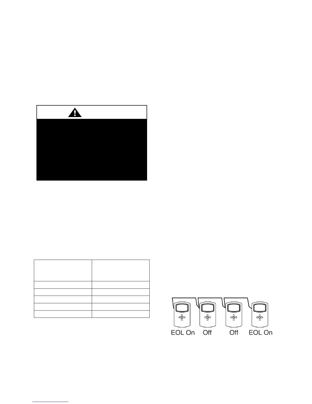
Controllers on the physical ends of the EIA-
485 wiring segment must have end-of-line
termination installed for proper network
operation. If a controller is at the physical
end of the MS/TP network line, set both the
EOL termination switches to the On position
on the back of the circuit board. If not on the
end, ensure that both switches are Off.
Figure 3 - MS/TP Network End-of-Line
Terminology
Disconnect all electrical power
sources before servicing the unit.
More than one power source may be
provided. Failure to do so may result
in injury or death from electrical
shock or entanglement in moving
parts.