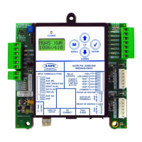
MODGAS-XWR2 Technical Guide
LCD DISPLAY SCREENS
27
Conguration Screens
Refer to the following map when navigating through the Conguration
Screens. From the CONFIG Screen, press
<ENTER> to scroll through
the screens and change setpoints. Use the <UP> and <DOWN> arrow
keys to change your selections. Press
<ENTER> to save any changes.
CONFIG
S/A MODE
AUTO or FORCED
STAND ALONE MODE
Auto or Forced. Default is Auto.
In order for the MODGAS-XWR2 to communicate with another
MODGAS-XWR2 or 12 Relay Expansion board, the MODGAS-XWR2
must be put in Forced Stand-Alone Mode.
STAGES
TOTAL 1 TO 19
NUMBER OF TOTAL STAGES
Range is 1 to 19. Default is 2.
Conguration Screens
OPRATION
NORMAL OR
MASTER
OPERATION MODE
Normal or Master. Default is Normal.
This screen is used to set a Primary MODGAS-XWR2 board as a
Master board. If only using one MODGAS-XWR2 board,
this should be set to Normal.
MODULATION
CONFIGURATION
MODULATION CONFIGURATION
Values are in the format xVyIGNzS, where x is the number of valves
(V), y is the number of ignitors (IGN) and z is the number of stages (S).
Values are 1V1IGN1S, 2V2IGN2S, 2V1IGN1S,
and 2V2IGN1S. Default is 1V1IGN1S.
The four congurations are explained in detail as follows:
1V1IGN1S: Valve conguration used to control one modulating gas
valve, which must be placed on the gas valve 1 header (attached to Heat
1 Relay). Additional stages may be added to Heat Relays 2, 3 & 4, or o
board if in a communication mode.
2V1IGN1S: Valve conguration used to control two modulating gas
valves (one on each header), in which the rst and second valves operate
together for one modulating stage. Both valves are connected to Heat 1
Relay, therefore, an additional xed stage may be added on board at the
Heat 2 Relay. Additional stages may be added on Heat Relays 3 & 4 or
o board for this conguration if it is in a communicating mode. NOTE:
Since both valves are attached to Heat 1 Relay, only one proof of ame
is required for both valves.
2V2IGN1S: Valve conguration used to control two modulating gas valves
(one on each header), in which the rst and second valves operate together
for one modulating stage. One valve is connected to Heat 1 Relay and
the second valve is connected to Heat 2 Relay. Additional stages may be
added to Heat Relays 3 & 4 or o board if it is in a communicating mode.
2V2IGN2S: Valve conguration used to control two modulating gas valves
(one on each header), in which the rst valve is modulating stage 1 (valve
1 header) and the second valve is modulating stage 2 (valve 2 header).
Additional stages may be added to Heat 3 & 4 Relays or o board if it is
in a communicating mode.
ADDRESS
1(138)
CURRENT BOARD ADDRESS
The rst number is the board address.
The number in parentheses is the E-BUS address.
Use this screen to set the Address for a Slave board.
Set the Address to 2 for a Slave board. Default is 1(138).
 Loading...