49
Wire control signals to the unit’s low
voltage terminal block located in the
controls compartment.
If any factory installed wiring must be
replaced, use a minimum 105°C type AWM
insulated conductors.
Variable Speed Compressors
Variable speed compressors with VFD
speed control are available on 55, 65 and 75-
140 ton units. Variable speed compressors
should not be operated outside the factory
determined frequency range. The factory
determined compressor VFD frequency
range is given below in Table 7.
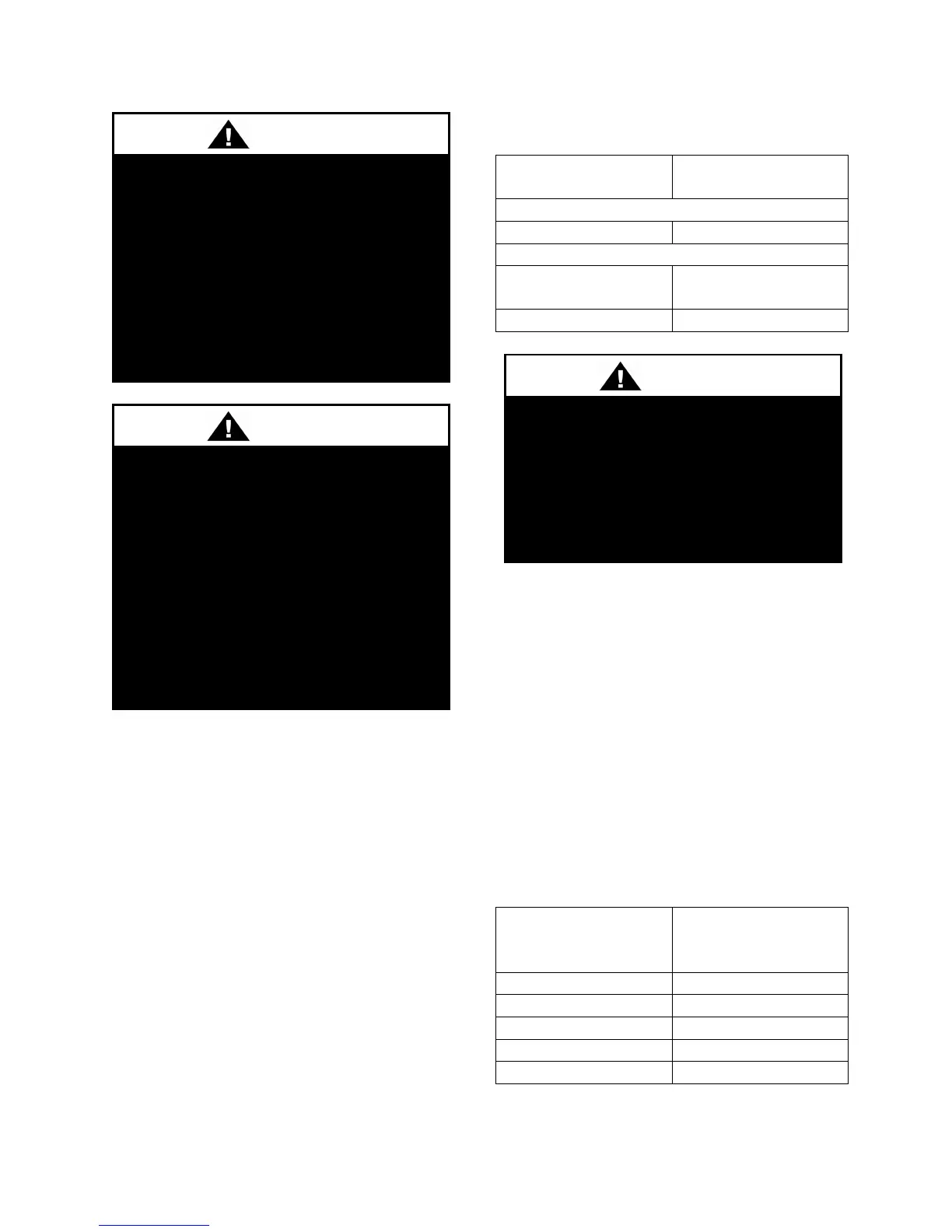
Table 7 - Variable Speed Compressor VFD
Frequency Range
Model (RN-)
Compressor VFD
Range (Hz)
208V, 230V and 380V Units
055, 065, 075, 090,
120, 130
35-75 Hz
Thermostat Control Wiring
If a thermostat is used for unit control,
thermostat should be located on an inside
wall 4-5 feet above the floor where it will
not be subjected to drafts, sun exposure, or
heat from electrical fixtures of appliances.
Control wiring must deliver adequate
voltage to components to assure proper
operation. Control voltage returning from
controller circuit must be a minimum of 21
VAC. To assure proper wiring use the
following chart to determine the allowable
wiring distances.
Table 8 - Control Wiring
- Copper Conductors
Allowable
No variable speed compressor shall
operate below 35 Hz. Operating
variable speed compressors outside
the frequency range specified in this
manual voids all warranties and may
result in compressor failure.
Scroll compressors are directional
and will be damaged by operation in
the wrong direction. Low pressure
switches on compressors have been
disconnected after factory testing.
Rotation should be checked by a
qualified service technician at startup
using suction and discharge pressure
gauges and any wiring alteration
should only be made at the unit
power connection.
Rotation must be checked on all
MOTORS AND COMPRESSORS of
three phase units. Supply fan,
exhaust fan, return fan, and
condenser fan motors should all be
checked by a qualified service
technician at startup and any wiring
alteration should only be made at the
unit power connection.

 Loading...


