93
Phase Loss LED = Green
5. On/Off LED = Green
Phase Loss LED = Green
1. On/Off LED = Alternating Green/Red
Powering up with no voltage present:
Phase Loss LED = Out
1. On/Off LED = Green
Going into trip condition after operating
conditions were good:
Phase Loss LED = Green
2. On/Off LED = Green Flashing
Phase Loss LED = Red
3. On/Off LED = Red
Phase Loss LED = Red
1. On/Off LED = Red
Going to good condition from trip condition
- automatic reset:
Phase Loss LED = Red
2. On/Off LED = Alt. G/R Flashing
Phase Loss LED = Green
3. On/Off LED = Green
Phase Loss LED = Green
1. On/Off LED = Red
Going to good condition from trip condition
- manual reset:
Phase Loss LED = Red
2. On/Off LED = Alt. G/R Flashing
Phase Loss LED = Green
3. Manual Reset button is pressed
4. On/Off LED = Green
Phase Loss LED = Green
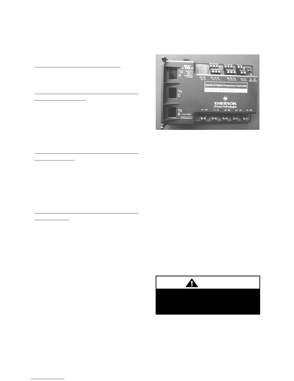
Variable Capacity Compressor
Controller
Units with variable capacity scroll
compressors may include the following
compressor controller. The following is an
explanation of the terminals and
troubleshooting alert flash codes of the
controller. For more information on the
compressor controller, see Emerson Climate
Bulletin AE8-1328.
Figure 50 - Variable Capacity Compressor
Controller
Low Voltage Terminals
Discharge Temperature Sensor
High Voltage Terminals
Digital Unloader Solenoid
The compressor controller modulates the
compressor unloader solenoid in an on/off
pattern according to the capacity demand
To avoid damaging the Compressor
Controller do not connect wires to
terminals C3, C4, T3, T4, T5, or T6.

 Loading...


