74
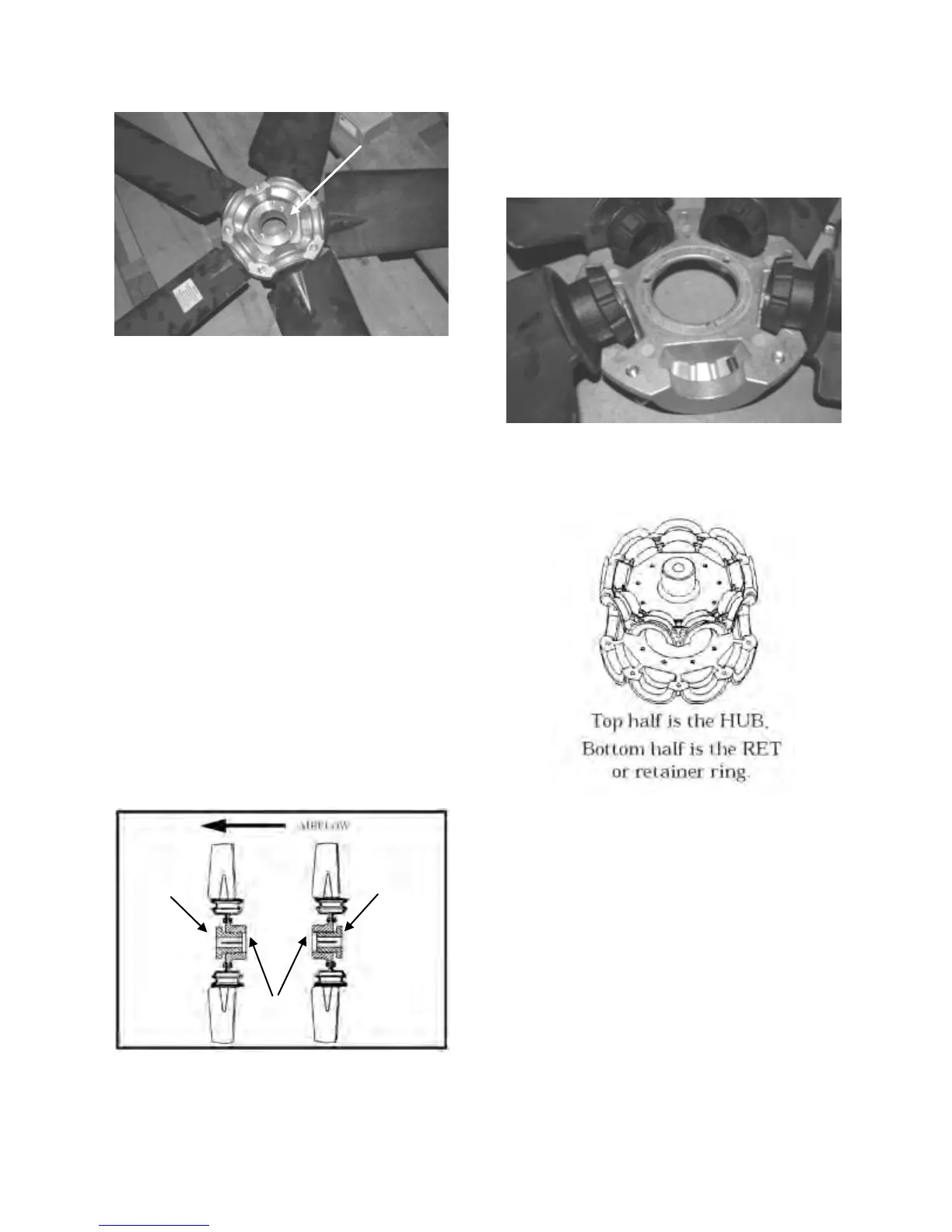
Figure 34 - Fan with the HUB on the Top
and RET on the Bottom
Step 3: Determine the direction of rotation
Right, R, is clockwise when facing the
discharge side of the fan and Left, L, is
counterclockwise when facing the discharge
side of the fan.
Step 4: Determine the bushing mount
location
The bushing mount is the center section of
the hub through which the fan is mounted to
the shaft, and typically contains either
setscrews or a center-tapered hole where the
bushing inserts.
Location A is with the bushing mount on air
inlet side of the fan.
Location B is with the bushing mount on air
discharge side of the fan.
Figure 35 - Bushing Mount Location
Step 5: Determine the pin location groove
Disassemble fan on a flat surface and note in
which groove the pin is located.
Figure 36 - RET with Pin in Groove 4
Step 6: Determine whether the pin is in the
HUB or RET
Figure 37 - Fan HUB and RET Castings
Mount
Bushing Bushing

 Loading...


