100
A factory installed pressure tap on the outlet
end of the gas valve can be used to verify a
manifold pressure of 3.5” w.c. for natural gas,
or 10.5” w.c. for propane.
Gas Pressure Regulator & Overpressure
Protection Device
A gas pressure regulator shall be installed if
natural gas supply pressure to the unit is
greater than 10.5” w.c. and less than 2 psi
(55.4” w.c.) and if propane gas supply
pressure is greater than 13” w.c. and less than
2 psi (55.4” w.c.). Regulators shall comply
with the latest edition of the Standard for Line
Pressure Regulators, ANSI Z21.80/CSA
6.22.
Both a gas pressure regulator and
overpressure protection device (OPD) shall
be installed if gas supply pressure to the unit
is greater than 2 psi (55.4” w.c.) and less than
5 psi (138.4” w.c.), in compliance with ANSI
Z21.80/CSA 6.22. For proper heater
operation, pressure to the regulator SHALL
NOT be greater than 5 psi (138.4” w.c.).
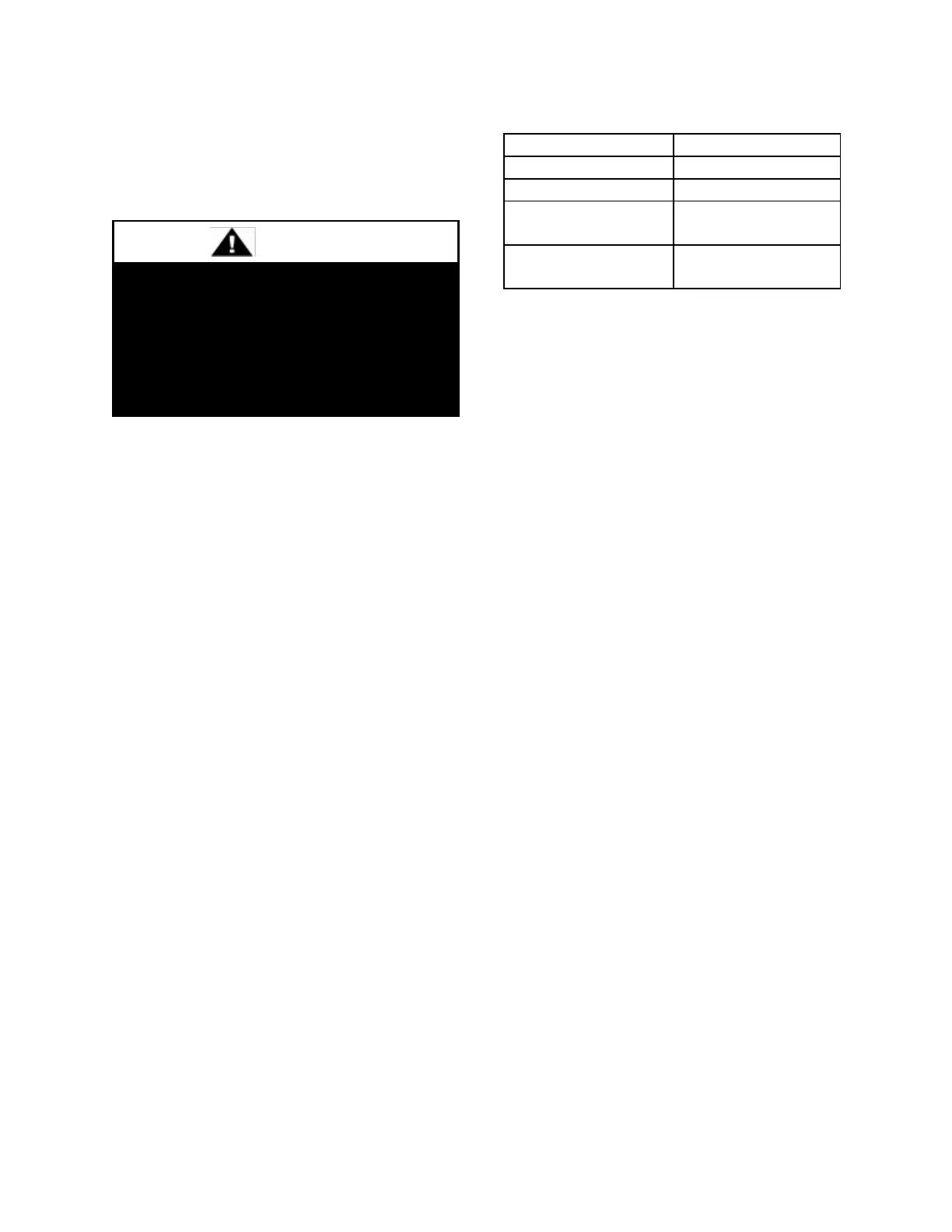
Piping Supports
Gas supply piping shall be supported directly
at the connection to the unit and at intervals
listed in the following table with metal straps,
blocks, or hooks. Piping shall not be strained
or bent.
Table 36 - Gas Piping Supports
Additional Gas Piping Considerations
Local codes will usually require a field
provided and installed manual main shutoff
valve and union external to the unit. Main
shutoff valve shall be labeled. Install a drip
leg near the unit connection to trap sediment
and condensate. Pipe joint compounds used
on all gas piping connections shall be
resistant to liquid petroleum gases. If flexible
gas piping to the unit, or in the unit, must be
replaced connectors cannot be reused, only
new connectors may be used.
Heat exchanger comes equipped with a
condensate drain which shall be plumbed to
the appropriate drain according to the (United
States) National Fuel Gas Code ANSI-
Z223.1/NFPA 54 or the current (Canada)
National Fuel & Propane Installation Code
CSA B149.1 or B149.2, the International
Building Code, and any applicable local and
regional codes and regulations.
The condensate drain connection is located
next to the gas entry location. For 6-50, 60
and 70 ton units, the heat exchanger
condensate drain connection from the unit is
a 5/8” barbed nylon elbow connection. For
55, 65 and 75-140 ton units, the heat
exchanger condensate drain connection from
the unit is a 3/4” PVC connection. For 55, 65
and 75-140 ton units, the heat exchanger
condensate drain can be tied into the
evaporator condensate drain, if code allows.
AAON gas fired heat exchangers are
designed to be non-condensing. These heat

 Loading...


