107
Removal
Disconnect all wiring on the heat exchanger.
Disconnect flex gas lines and pull out of the
way.
Remove screws around the perimeter of the
heat exchanger face plate that connect it to
the unit. Remove only the outermost screws.
Pull the heat exchanger straight back and out
of the unit. It may be necessary to remove
some of the control door jambs.
Reinstallation
Ensure that the neoprene isolator is installed
around the perimeter of the heat exchanger.
Insert heat exchanger into opening so that the
back of the main plate is against the unit
bulkhead.
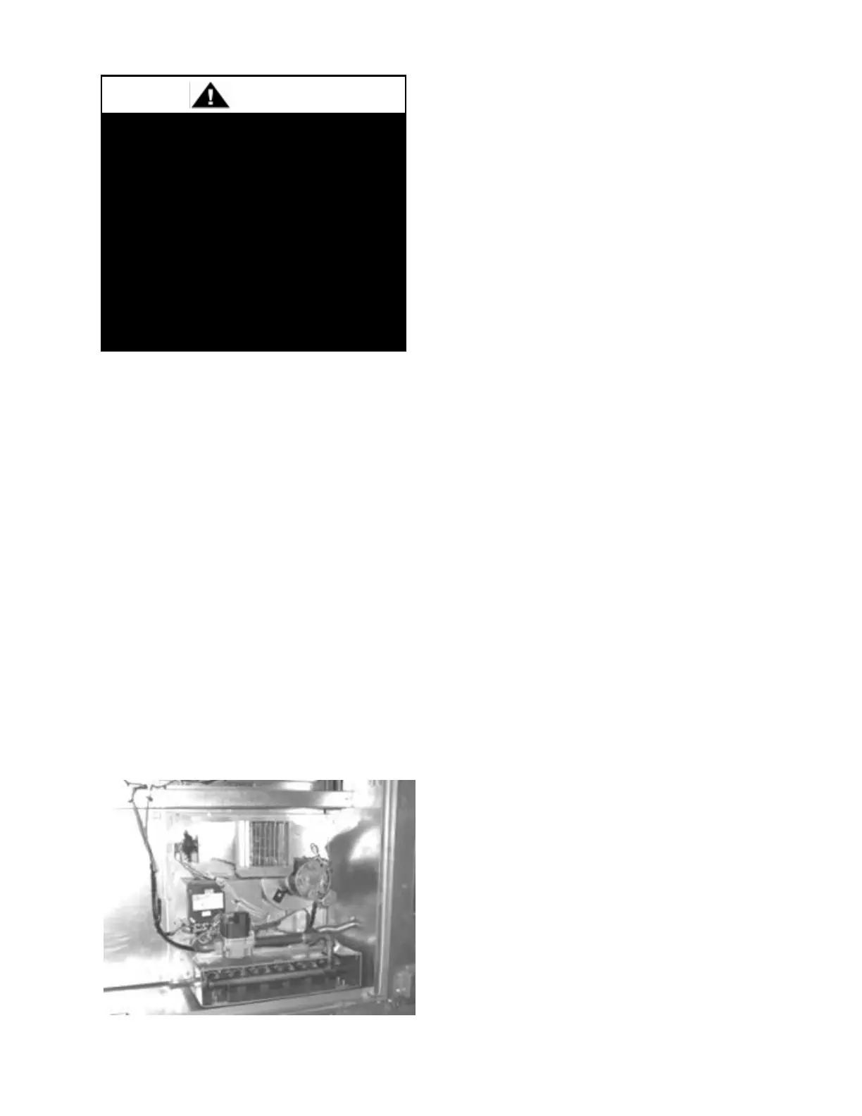
Figure 59 - Gas Heat Exchanger
Attach the heat exchanger to the bulkhead
using the holes around the perimeter.
Connect flex gas lines to the piping on the
heat exchanger. If flexible gas piping in the
unit must be replaced connectors cannot be
reused, only new connectors may be used.
Connect wiring per the wiring diagram on the
controls compartment door.
Purge gas lines to the gas valves at the unit.
The gas pipe in the unit shall be
checked for leaks before startup. Leak
checking is the responsibility of the
installing contractor. All connections
shall be checked for leaks annually
after installation. Failure to leak check
could result in fire, explosion, or other

 Loading...


