45
Electrical
Verify the unit nameplate agrees with power supply. Connect power and control wiring to the unit
as shown in Figure 27 and Figure 28, and in the unit specific wiring diagram, which shows factory
and field wiring and is attached to the inside of the door of the controls compartment.
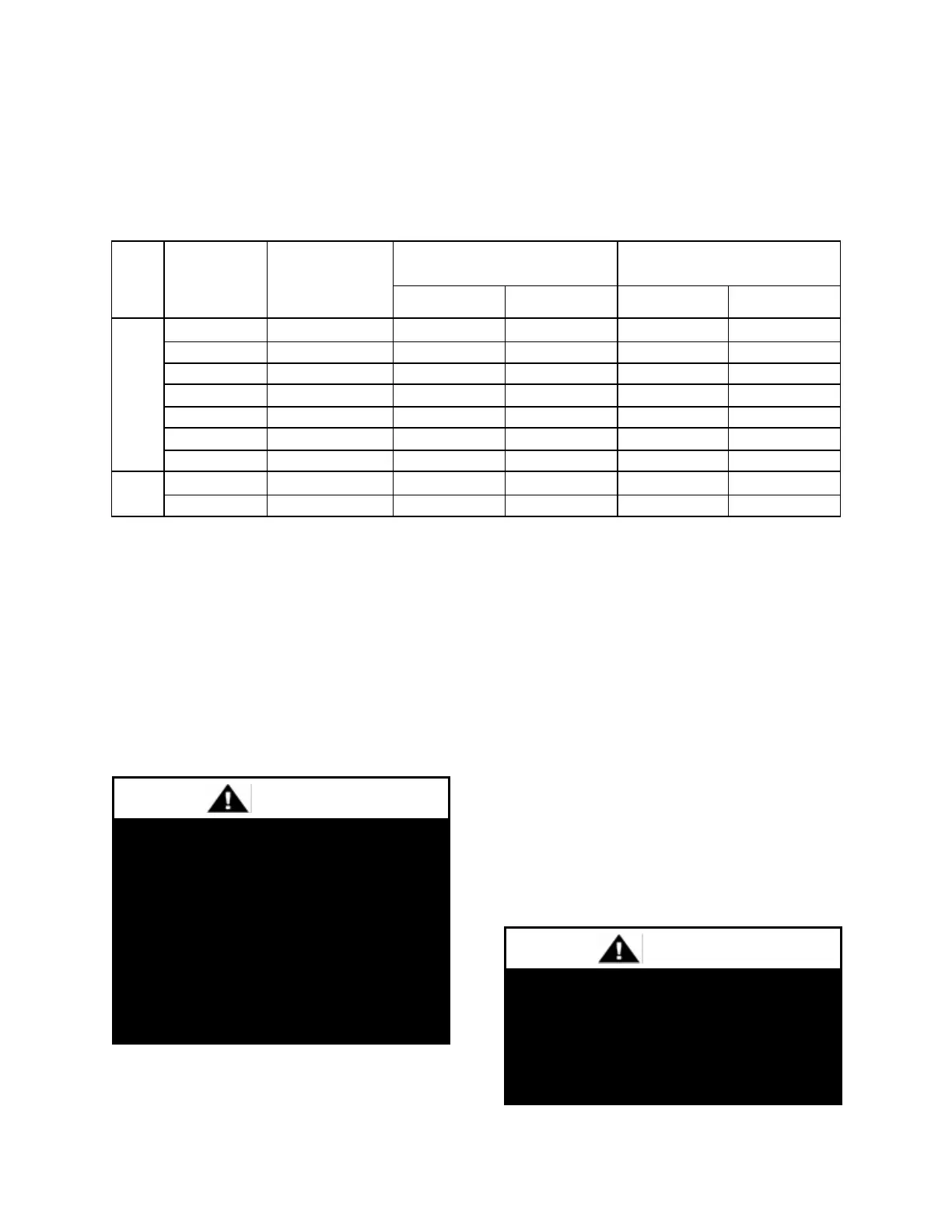
Table 6 - Nameplate Voltage Markings & Tolerances
Notes:
1. Operating voltage is the min and max voltage for which the unit can function. Never
operate outside of this min and max voltage.
2. The Acceptable Performance Range is the min and max voltage for which the unit
performance is designed and rated to give acceptable performance.
Route power and control wiring, separately,
through the utility entry in the base of the
unit. Do not run power and signal wires in the
same conduit.
Route power and control wiring, separately,
through the utility entry in the base of the
unit. Do not run power and control signal
wires in the same conduit. The utility entry
on 9-25 and 30 ton units is located in the unit
base in the front right hand corner of the unit
(compressor compartment). The utility entry
on 26 and 31-70 ton units is located in the unit
base in the front left hand corner in the unit
(controls compartment). The utility entry on
55, 65 and 75-140 ton units is located in the
center front of the unit. See unit drawing for
specific location.
Electric shock hazard. Before
attempting to perform any installation,
service, or maintenance, shut off all
electrical power to the unit at the
disconnect switches. Unit may have
multiple power supplies. Failure to
disconnect power could result in
dangerous operation, serious injury,
death, or property damage.
Installing Contractor is responsible for
proper sealing of the electrical and
gas entries into the unit Failure to seal
the entries may result in damage to
the unit and property.