bdiRDI
JTAG interface for RDI Debuggers, BDI1000 User Manual 10
© Copyright 1999-2003 by ABATRON AG V 1.10
2.2.2 Power Supply from Target System
The BDI1000 needs to be supplied between 2.5V and 5V via TARGET A connector. This mode can
only be used when the target system runs between 2.5V and 5V and the pin «Vcc Target» is able to
deliver a current up to:
• 900mA@2.5Vcc Target
• 700mA@3.3Vcc Target
• 450mA@5.0Vcc Target
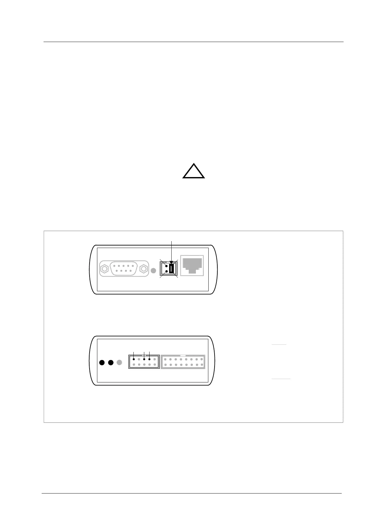
For pin description and layout see chapter 2.1 «Connecting the BDI1000 to Target». Insert the en-
closed Jumper as shown in figure below. Please ensure that the jumper is inserted correctly.
For error-free operation, the power supply to the BDI1000 must be between 2.5V and 5V DC. The
maximal tolerable supply voltage is 5.25 VDC. Any higher voltage or a wrong polarity might
destroy the electronics.
!
POWER Connetcor
1 - Vcc BDI1000 (+2.5 ... +5V)
2 - Vcc Target (+2.5 ... +5V)
3 - GROUND
4 - NOT USED
The green LEDs «BDI» and «TRGT» marked light up when target is powered up
and the jumper is inserted correctly
RS232 LI POWER 10 BASE-T
1
2
3
4
TARGET A TARGET B
BDI
TRGT
MODE
Jumper
359
1 - Reserved
2 - TRST
3 - GROUND
4 - TCK
5 - GROUND
6 - TMS
7 - RESET
8 - TDI
9 - Vcc Target
10 - TDO
Target A Connector
 Loading...