bdi
RDI
JTAG interface for RDI Debuggers, BDI1000 User Manual 4
© Copyright 1999-2003 by ABATRON AG V 1.10
2 Installation
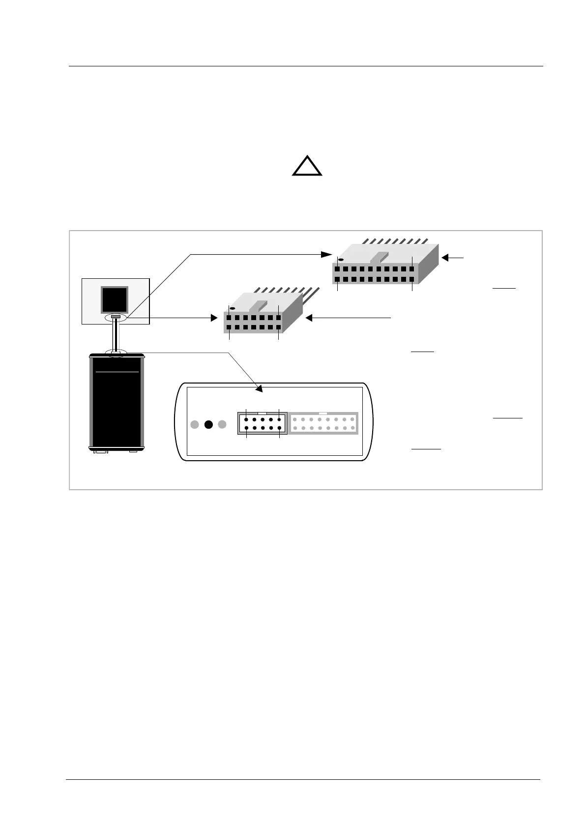
2.1 Connecting the BDI1000 to Target
The enclosed cables to the target system are designed for the ARM Development Boards. In case
where the target system has the same connector layout, the cable (14 pin or 20 pin) can be directly
connected.
In order to ensure reliable operation of the BDI (EMC, runtimes, etc.) the target cable length must not
exceed 20 cm (8").
TARGET A connector signals see table on next page.
!
BDI1000
AA
AA
bb
bb
aa
aa
tt
tt
rr
rr
oo
oo
nn
nn
AA
AA
GG
GG
SS
SS
ww
ww
ii
ii
ss
ss
ss
ss
MM
MM
aa
aa
dd
dd
ee
ee
Target System
ARM
1
13
14
2
The green LED «TRGT» marked light up when target is powered up
14 pin Target
Connector
1 - Vcc Target
2 - GROUND
3 - TRST
4 - GROUND
5 - TDI
6 - NC
7 - TMS
8 - NC
9 - TCK
10 - NC
11 - TDO
12 - RESET
13 - NC
14 - NC
1 - Vcc Target
2 - NC
3 - TRST
4 - NC
5 - TDI
6 - NC
7 - TMS
8 - GROUND
9 - TCK
10 - GROUND
11 - NC
12 - NC
13 - TDO
14 - NC
15 - RESET
16 - NC
17 - NC
18 - NC
19 - NC
20 - NC
20 pin Multi-ICE
Connector
1
19
20
2
BDI TARGET A TARGET B
9 1
10
2
BDI
TRGT
MODE