bdi
RDI
JTAG interface for RDI Debuggers, BDI1000 User Manual 9
© Copyright 1999-2003 by ABATRON AG V 1.10
2.2 Connecting the BDI1000 to Power Supply
2.2.1 External Power Supply
The BDI1000 needs to be supplied
between 2.5V and 5V via the POWER connector. The available
power supply from Abatron (option) or the enclosed power cable can be directly connected. In order
to ensure reliable operation of the BDI1000, keep the power supply cable as short as possible.
For error-free operation, the power supply to the BDI1000 must be between 2.5V and 5V DC. The
maximal tolerable supply voltage is 5.25 VDC. Any higher voltage or a wrong polarity might
destroy the electronics.
Please switch on the system in the following sequence:
• 1 --> external power supply
• 2 --> target system
!
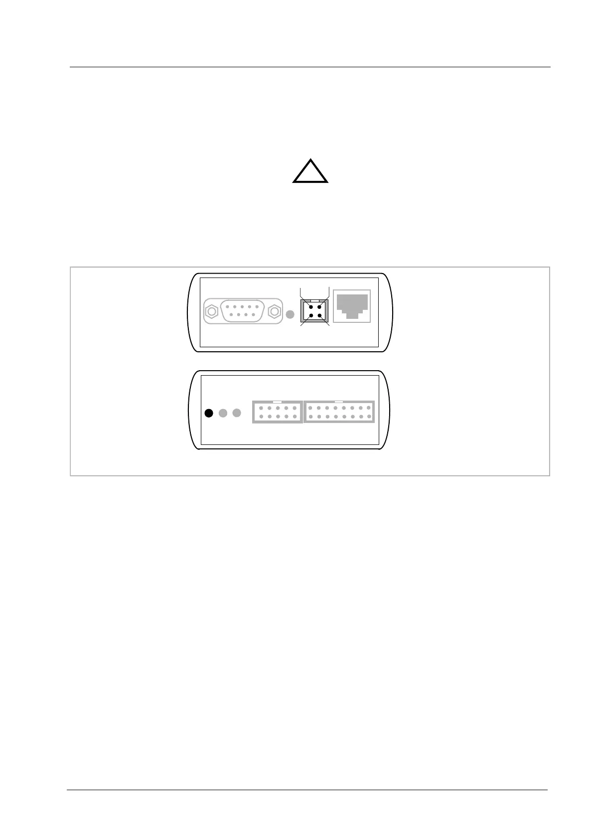
POWER Connector
1 - Vcc (+2.5 ... +5V)
2 - VccTGT
3 - GROUND
4 - NOT USED
The green LED «BDI» marked light up when power (2.5 – 5V) is connected to the BDI1000
RS232 LI POWER 10 BASE-T
1 Vcc
2
GND 3
4
TARGET A TARGET B
BDI
TRGT
MODE